1: Setup & Connections • 8
©2008 Axia Audio — Rev. 3.0
on-screen time display between 12-hour (normal-
style) and 24-hour (military-style) timekeeping.
Time Zone GMT+: Use this field to set the glob-
al time zone your station is located in, relative to
Greenwich Mean Time.
Time And A Word: The term “Greenwich Mean
Time” refers to Britain’s Royal Greenwich Obser-
vatory, which lies athwart the Prime Meridian.
Time at this location is referred to as “base time,”
to which all other time zones are relative. GMT is
properly referred to as UTC - “Coordinated Uni-
versal Time.”
If you’re at a loss as to what the GMT offset is
for your location, a complete list is located on-
line at www.wikipedia.org . Enter a search for
“Time Zone” and scroll down the resulting page.
Countdown From: When the operator enters an
interval of time into this field, Element’s count-
down timer will count backwards from this num-
ber to zero upon exit of this screen.
Show Tenths On: Allows you to set the count-
down and elapsed-time counters to show or hide
tenths-of-a-second displays.
A Note About Metering: Element’s bargraph
meters feature true VU meter ballistics, though
with an expanded scale. The red line at -20dBFS
corresponds to the 0dB mark on a traditional
analog meter. Just as with a traditional analog
meter, the 300ms time-constant lter speci-
ed in the VU standard means that peaks are
much higher than the meter indicates. Depend-
ing upon the nature of the program material,
transient peaks will be 9-15dB higher than the
VU-ltered average. This is why modern con-
soles, including Element, have 20dB headroom
above the nominal operating level. Some of this
headroom is used to cover the peak transients
the VU meter can’t see, and some is used for
operator error or surprise margin. (ie, the well-
known “excited sportscaster scream”.)
By default, Element meters are set to display
both average and peak levels, the average be-
ing represented by the main bargraph display,
and the peaks represented by the small oating
line that appears above them.
Show Meter Peaks: Allows you to turn Ele-
ment’s Peak meter display on or off. Yes dis-
plays peaks; No does not.
»
»
»
»
Push the Save knob to commit to the changes you’ve
made. You may do this at any time, after changing
any option to apply the change immediately.
Push the Exit knob to leave the Clock & Timer Op-
tions screen.
The next section will walk you through setting up
your StudioEngine.
StudioEngine Quick Setup
Connections and IP Conguration
Connections
Note: We recommend leaving 1RU of “breath-
ing space” for ventilation above and below the
StudioEngine when you rack-mount the unit.
Using the supplied AC power cord, connect the
StudioEngine to the mains. Route a length of CAT- 6 ca-
ble from StudioEngine to a Gigabit port on your studio’s
Ethernet switch, but don’t connect it yet.
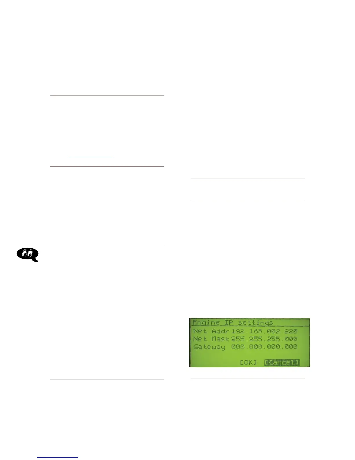
IP Conguration
Power on your StudioEngine; the front-panel display
will indicate the boot-up sequence. When the screen
displays IP address and network connection informa-
tion, push the control knob to call the Main Menu.
Turn the control knob to highlight Option #4, IP
Settings (Figure 1-14), and push to select.
Figure 1-14: StudioEngine IP conguration screen.
Push the control knob and you’ll see that the first
line of the display (marked Net Addr) is underlined.
Push the knob again to select this line.
You’ll see a flashing underline under the first digit
•
•
1.
2.
3.
4.