1: Setup & Connections • 2
©2008 Axia Audio — Rev. 3.0
Element Preliminary Setup
If you haven’t done so yet, it’s time to get your
Element out of its packing crate. This is a two-person
job, so grab a partner.
Important: Like any electronic device, Element
can be affected by static electricity. Use of a
personal grounding device is strongly recom-
mended during transport.
Position one person at each end of Element and,
grasping the metal enclosure at the bottom, simulta-
neously lift upward out of the shipping crate. Remove
packing materials and store them in the crate for future
use. Carefully lower Element into your counter top cut-
out, taking care to lower both sides at an equal rate to
avoid becoming jammed in the cabinetry.
Important: Element is a drop-in style control
surface and requires a countertop cutout. For
cutout dimensions, please refer to Appendix A.
Unpack the GPIO Node/Power Supply that came
with your Element and place it in its rack.
Connections and IP Conguration
Connections
Cable connections for Element are entirely different
from any other mixing surface you may be familiar with.
There are no audio inputs; Element needs only a single
data / power connection to operate.
Important: Your Element MUST be ground-
ed. Grounding reduces the risk of electric
shock by providing a “path of least resistance”
for electric current. Improper grounding can
result in a risk of electric shock.
Check with a qualied electrician if you are in
doubt about how to properly ground this equip-
ment. If your local electrical code prohibits the
use of a Station Ground for this purpose, as de-
scribed above, use the specic “Safety Ground”
your local regulations mandate.
Rack-mount the GPIO Node/Power Supply unit
and connect it to a 100Base-T port on your studio’s
Ethernet switch using CAT. 6 cable. Do not power up
the Power Supply yet.
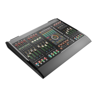
Figure 1-2: Accessing Element’s connection panel.
Element must be connected to a grounded metal per-
manent wiring system or other equipment grounding
conductor using the threaded grounding stud located
inside the connections bay. Open the bay by flipping
open the overbridge above the faders, as shown in
Figure 1-2. For ground sources, we recommend, in
order of preference:
“Station Ground,” the heavy copper strap found in
the walls and floors of many radio studios.
1.
2.
»
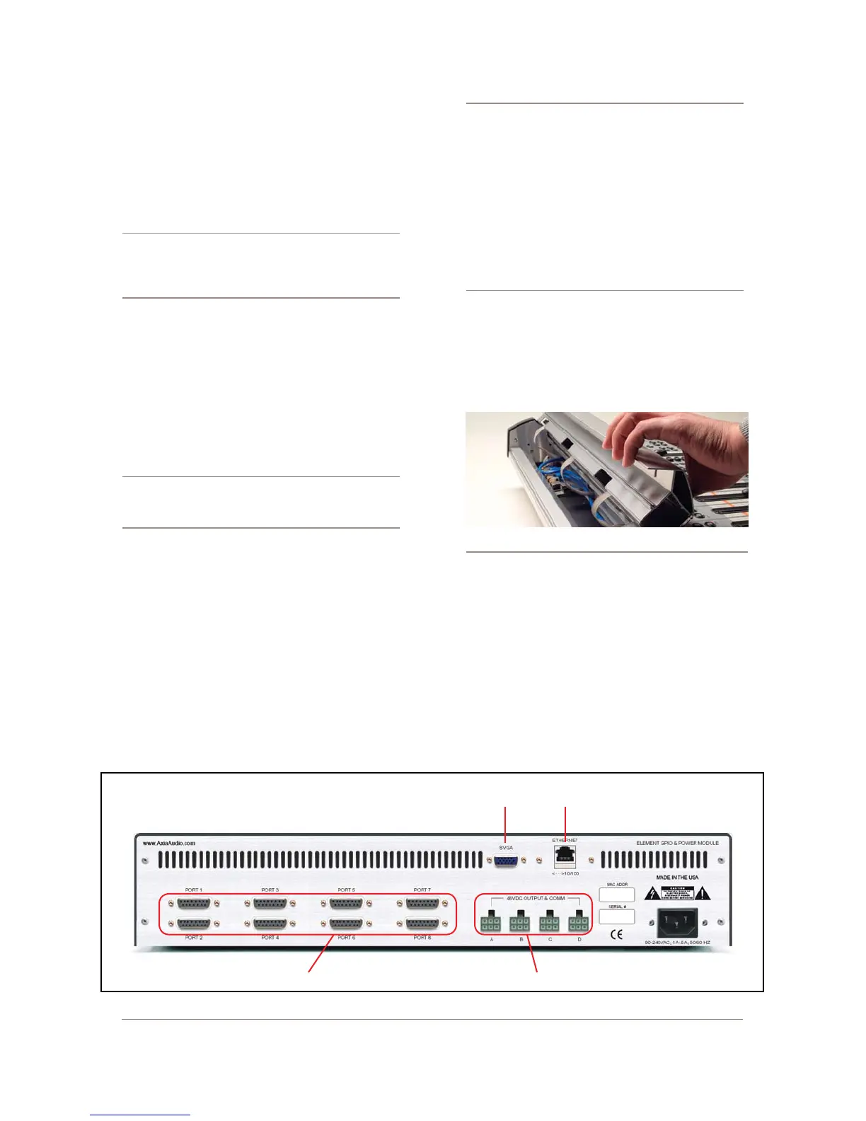
Figure 1-1: Rear panel of Element GPIO/Power Supply showing connections.
Ethernet
Port
GPIO Ports DC Power - CANbus to Element
VGA
Display