1: Setup & Connections • 5
©2008 Axia Audio — Rev. 3.0
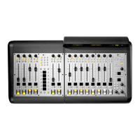
Additionally, whenever numeric input is required
(like entering IP addresses), you can use the numeric
keypad located just above the Navigation Keys (Figure
1-10) to enter numbers directly.
Figure 1-10: Master Module numeric keypad.
IP Address Conguration
Using your IP Assignment Worksheet, you’ll
now choose an IP address for both your Element and
StudioEngine. You must make sure that IP addresses
for both Engine and Surface are in the same IP network,
and are both valid Unicast addresses. For example:
192.168.2.101: Engine
192.168.2.201: Surface
Both addresses belong to 192.168.2.x IP network,
and so will work for our application.
Note: “Gateway” settings on Livewire equip-
ment are optional. They may be left blank un-
less you intend to access the StudioEngine’s
conguration utility remotely, from outside your
network. Should you desire to do so, enter the
IP address of your master router (the one with
external network connections) whenever you’re
given the option to enter a gateway IP address.
Note: Element v2.x software supports redun-
dant NTP servers. Use the second eld in the IP
Address Book to enter the address of a backup
server.
Once you’ve determined the IP addresses you’ll as-
sign, turn on the Element power supply and the attached
VGA monitor.
Setting IP using the Standard Monitor Module
When Element has completed its start cycle (meter
screen appears), find the section marked Global Op-
»
»
tions on the Monitor Module. Press and hold the key
marked Fader Options located in the top right corner
of the module for five seconds to enter the IP Address
Book (Figure 1-11).
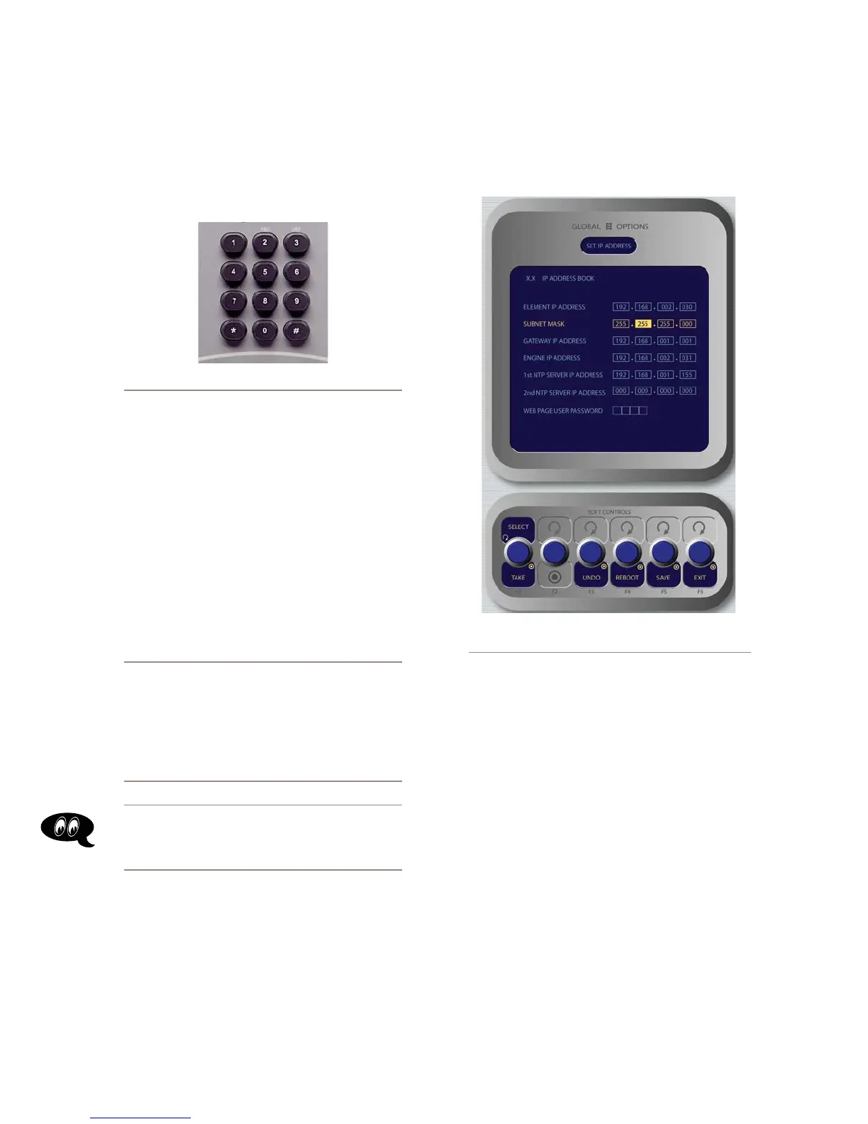
Figure 1-11: IP Address Book,
Standard Monitor Module
To set the IP address, rotate the leftmost SoftKnob to
highlight the line titled “Element IP Address” and push
the knob to select that line. Now use the numeric pad to
enter the IP address. Press the leftmost SoftKey again
to “take” the new IP value. Repeat this process to set the
subnet mask value.
Continue down the screen and, in the same way, en-
ter the other fields’ values as appropriate.
Rotate the Select/Set SoftKnob to scroll through
the list of available options. To select an option to
modify, push this knob. While modifying an options,
rotate the knob to change an option’s value, and push
the knob to move to the next field. Available options
include:
Element IP Address: Every piece of Livewire
gear must have its own unique IP Address. Set
the IP Address for each Element in this field.
•
»