FAQ / Diagnostics / Maintenance • 140
©2008 Axia Audio — Rev. 3.0
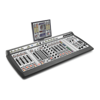
ture Mode, press and hold the Help key on the Master
Module for 5 seconds. The alphanumeric displays will
change to read Capture Mode; this enumerates all of
the installed faders in the control surface. Press the En-
ter key to exit Capture Mode; your new module is active
and your Element is ready to use.
Module Diagnostics
Element software contains a hidden routine that al-
lows you to perform fader, lamp and alphanumeric dis-
play diagnostics on each module should you suspect that
one of these items requires service.
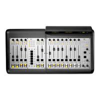
To enter the diagnostic mode, press and hold the
Help and Right Arrow keys found on Element’s Moni-
tor Module for 5 seconds.
Figure C-13: Press and hold these keys for 5 seconds
to enter module diagnostic mode.
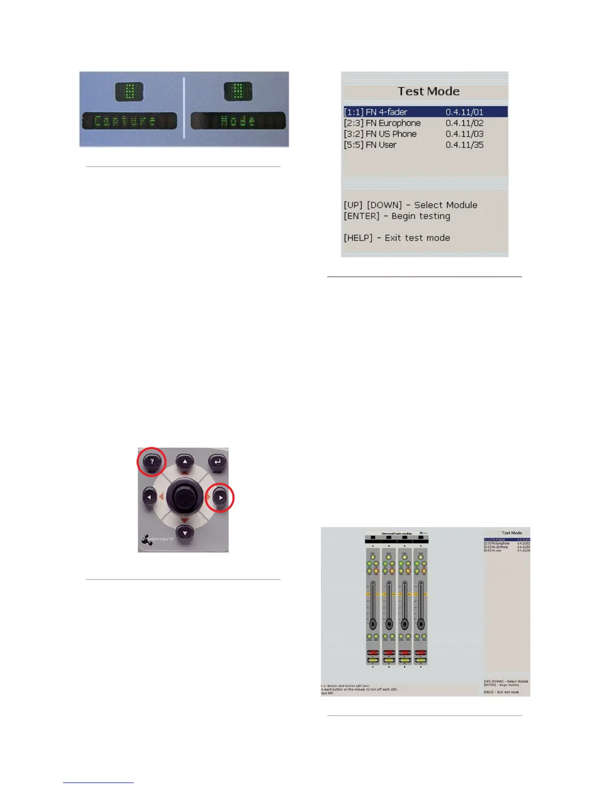
Upon entering the lamp diagnostic mode, the VGA
monitor connected to Element will display an initial
screen with a list of all installed modules (as shown in
Figure C-14). You’ll see a description of the type of each
module; preceding the description are a set of numbers
in brackets.
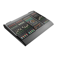
To begin fader diagnostics, use the Arrow keys to
highlight the fader you wish to test and press the Enter
key. You will see, onscreen, a graphical representation of
the selected module’s controls, including faders, lighted
selection keys and on/off switches.
In the first phase of the test, all of the module’s lamps
are lit and you are instructed to turn each one off. This
serves as a combination lamp and switch test.
When the lamp/switch test is complete, you’ll be
prompted to perform a fader operation test. As you move
the faders on the module being tested, you will see their
onscreen images move as well, and the alpha displays on
Element itself will display changing encoder values as
the faders are moved.
When you have finished testing a module, you have
Figure C-12: Alpha display indicates Capture Mode
Figure C-14: Module diagnostic selection
Figure C-15: Module lamp test