FAQ / Diagnostics / Maintenance • 141
©2008 Axia Audio — Rev. 3.0
the option of testing other modules, or of exiting the test
routine.
Fader Cleaning Procedures
Element’s single-element, conductive-plastic faders
were chosen for their long life and reliable operation, but
jocks will be jocks: it’s inevitable that sooner or later
you’ll need to pull a fader for cleaning.
There are no replaceable parts in the faders used in
Element. If fader movement has become rough, either
the lubricant on the glide rails has evaporated or foreign
material has gotten into the fader. Dow Corning 510 is
the preferred glide rail lubricant as it will not migrate to
the contact fingers like other lubricating oils.
Element modules can be serviced “hot.” If you
disconnect a module, the StudioEngine will retain the
faders’ most recent settings until the hardware is recon-
nected.
Tools and supplies you will need to remove and ser-
vice a fader:
A
1
/16” hex wrench (for fader removal)
A 2.5 mm hex wrench (for module removal)
A jeweler’s screwdriver (
5
/64” or smaller)
Cotton swabs
Dow Corning 510 lubricating oil
Fader Disassembly and Cleaning
Use the 2.5 mm hex wrench to remove the re-
taining screw(s) at the top of the module requir-
ing service. With the screwes removed, lift the
module at the top, tilting it upward, and pull the
locating tab at the bottom of the module from the
mounting channel.
Turn the module over and locate the ribbon cable
that connects the module to its overbridge display
(if present). Gently press the “ears” on each side
of the board connector to release the cable.
Locate and disconnect the RJ45 patch cable that
connects the module to Element’s connection
»
»
»
»
»
1.
2.
3.
panel.
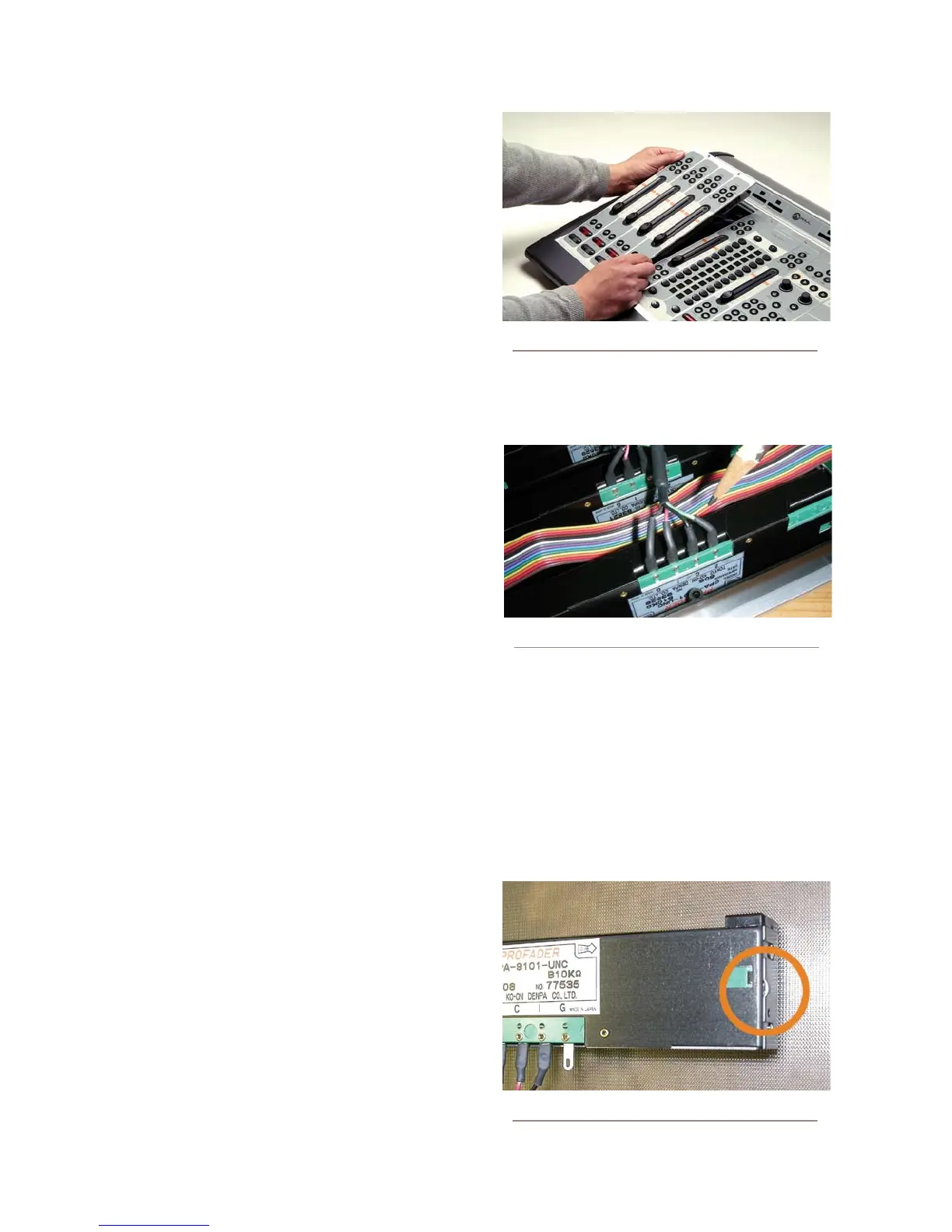
Remove the four-conductor fader cable from the
pins on the bottom of the fader (Figure C-17).
Now that the fader is disconnected, turn the mod-
ule right-side up. Remove the knob from the fader
to be serviced by pulling gently upward.
Using the
1
/16” hex wrench, remove the two hex
screws at the top and bottom of the fader slot.
The fader will drop out from the bottom of the
module.
Lay the fader assembly on your work surface, la-
bel-side up. Remove the snap-on fader assembly
4.
5.
6.
7.
Figure C-16: Tilt module up to remove from frame.
Figure C-17: Remove the fader connector cable
Figure C-18: Pry point on fader cover