Introduction • ix
©2008 Axia Audio — Rev. 3.0
Quickstart
The following chapters of this manual will give you
an in-depth understanding of the capabilities of your
new Element, from installation to advanced functions.
But maybe you’re the sort who really doesn’t want to
read a manual – you want to open up the boxes and play!
This Quickstart section isn’t meant to take the place of
the following manual chapters, but it will help you get
everything connected fast, and point you to the parts
of the manual you’ll need to get up and running with a
minimum of fuss.
Making Connections
You’ve probably unpacked your boxes and are sitting
next to a pile of Axia gear, wondereing what to do first.
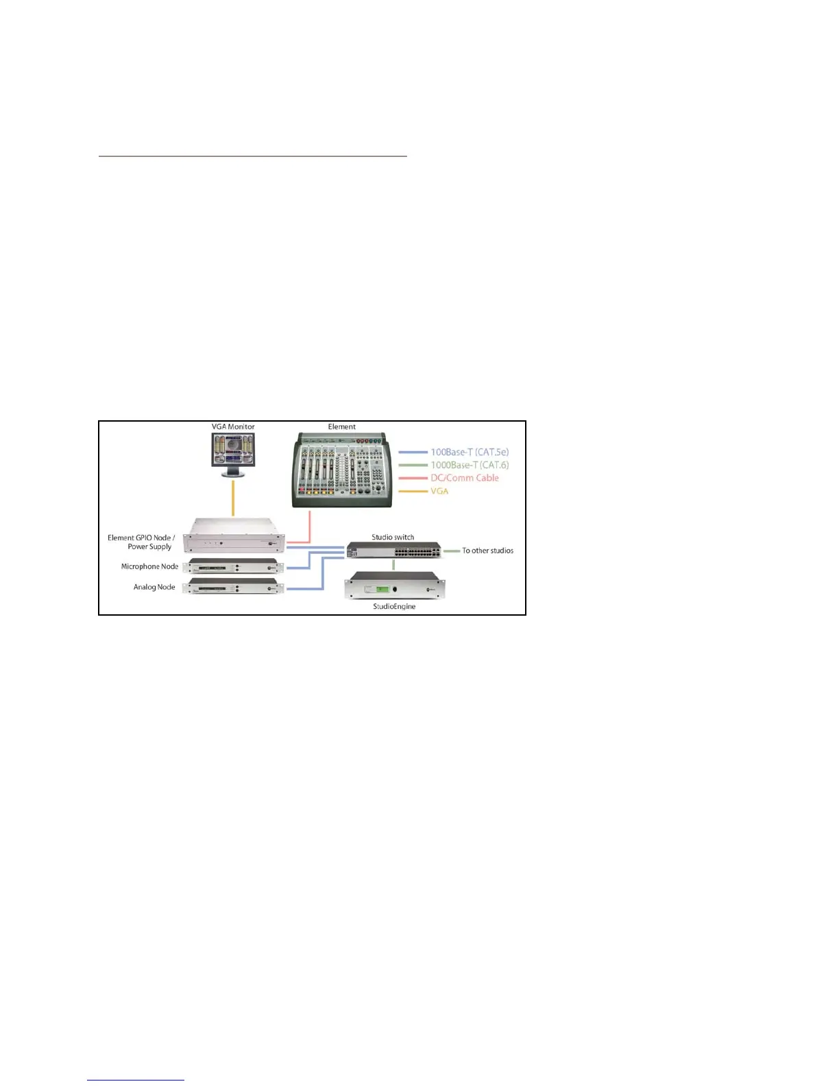
Take a look at the diagram above: it represents a typ-
ical Livewire-connected radio studio. Here’s what you
should do to get going:
Using CAT.5e or CAT.6 Ethernet cable, connect
all of your Axia Audio Nodes (Analog, AES/EBU,
Microphone and Router Selector) to 100Base-T
ports on your studio’s Ethernet switch.
Use CAT.6 Ethernet cable to connect your
StudioEngine to a Gigabit (1000Base-T) port on
the switch.
Use another CAT.5e or CAT.6 cable to connect
the Ethernet port on the back of the Element
GPIO Node/Power Supply to a 100Base-T port
1.
2.
3.
on the switch.
Packed with your Element is a cable with 6-pin
Molex™ connectors. This is the power/commu-
nications cable. Lift the Element meter panel and
connect the end of the cable without the strain
relief to the corresponding port on the Element
connection panel. Connect the other end of the
cable to one of the jacks labeled “48VDC OUT-
PUT & COMM” on the back of your Element
GPIO Node/Power Supply unit.
Connect all Audio Node power cords and plug
them into your studio’s power receptacles.
“Capture” your console using the instructions in
Chapter 1, Page 3 of this manual.
Follow the instructions found in Chapter 1 to
configure IP address settings for El-
ement and the StudioEngine.
Refer to the User’s Manuals
packed with your other Axia
Audio Nodes for information on
how to configure IP addresses for
these units.
Software Setup
When you’ve completed physi-
cally connecting your Axia hardware, read through the
remainder of this manual to begin configuring the soft-
ware options that determine how your new Element will
operate.
Chapter 2, “Configuring Inputs,” explains how to
generate Source Profiles and construct backfeeds for
selected sources.
Chapter 3, “Configuring GPIO,” tells how to associ-
ate routable logic commands with any audio source.
Chapter 4, “Element Operations,” takes you under
the hood to explore in-depth software options.
Chapter 5, “Show Profiles,” illustrates how to set and
save unique “snapshots” tailored for specific opera-
tional situations that can be recalled whenever the
need arises.
Enjoy your new Element! q
4.
5.
6.
7.
8.
•
•
•
•