3: Conguring GPIO • 34
©2008 Axia Audio — Rev. 3.0
Assigning GPIO to a Source
As you’ve seen by studying the previous pages, a lot
of the work of assigning logic to a source is done for you;
once a GPIO port is linked with a Source Profile, all that
remains to do is to solder cables connecting the GPIO’s
DB-15 connectors to the device’s control interface.
So, how do you link a GPIO port with a Source Pro-
file? It’s very easy; let’s do it step-by-step.
Note: This procedure assumes that you have
already dened at least one Source Prole using
the instructions outlined in Chapter Two.
Open your Web browser and enter the IP address of
your Element console. Choose GPIO Conguration
from the Element Control Center menu. Enter your
password if prompted (default login is “user”, leave
the password field blank).
If you haven’t previously assigned any GPIO ports,
the GPIO definitions screen will be blank. Notice the
status indicators at the top of the page, showing the
state of the input and output pins of each port. Click
on the list icon to the right of an unused line.
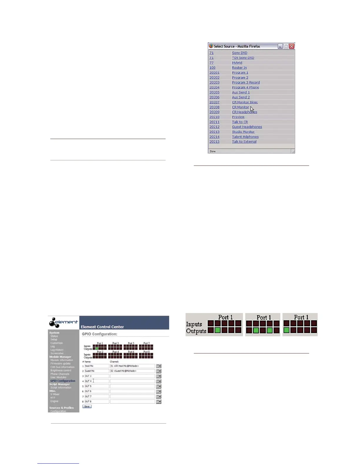
When you click on any list icon, a small popup win-
dow will open, enumerating all of the audio sourc-
es available on the Livewire network (Figure 3-3).
Choose the source you wish to associate with a GPIO
port by clicking on it; the window will close and the
source’s name and channel number will appear in
1.
2.
3.
the Channel box.
Type a descriptive name in the Name field, and click
on the Save button at the bottom of the page.
Look at the page-top status indicator for Port 1.
You’ll see that one of the pin status indicators is
lit in green; this means that the port is now send-
ing a GPIO logic state of “true” through this
pin. Assign the source for which you just created
a GPIO link to a Element channel; operate the
On and Off keys for the channel and watch the
pin status indicators change as you do so.
The source we’ve been using for this demonstra-
tion is a telephone hybrid; we can now observe the
pin status indicators change as we turn the channel
on and off, as shown in Figure 3-4.
Referring to the Hybrid Logic Chart on Page 28, we
can see that when the Element channel is Off, the
indicator representing Output Pin 2 – the Off Lamp
logic command – is high. Turning the channel On,
we see Pin 4 pulse briefly before Pin 1 goes high:
the GPIO has just sent a Start pulse, then lit the
On Lamp. If you turn the channel Off again, you’ll
observe a Stop pulse, and the Off Lamp command
4.
5.
Figure 3-2: GPIO denitions page
Figure 3-3: GPIO Select Source popup list
Figure 3-4: Pin status indicators showing
GPIO port activity