Accessory User Panels • 157
©2008 Axia Audio — Rev. 3.0
nection described above in “Installation.”
Using a PC connected to the Axia network, enter the
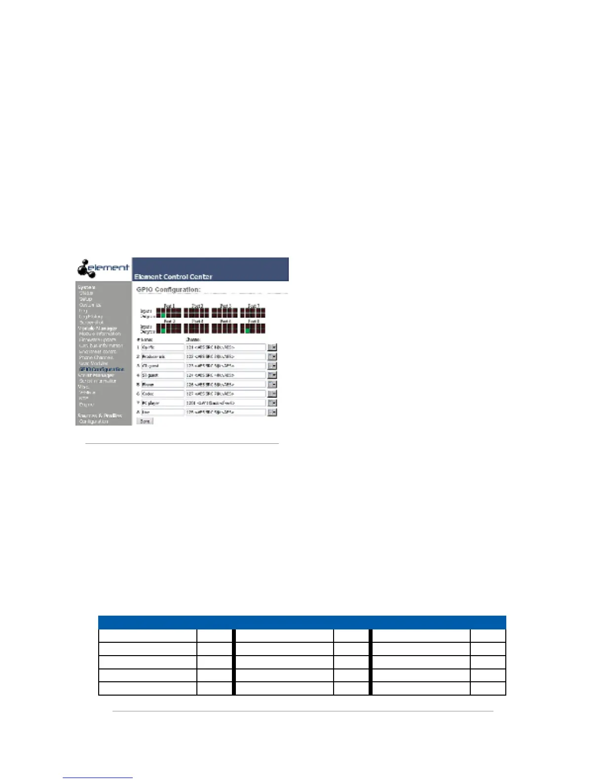
configuration page for your Element and select the GPIO
Configuration section.
In the GPIO Configuration page, you will see eight
listings that correspond to the eight ports that are on the
back of the Element Power Supply. Create a name on the
listing that corresponds to the port to which you wired
your Mic Control Panel, and enter the channel number
of the mic source you want it to control.
Figure E-5: GPIO status indications
Now, assign the Mic channel you’re working with to
one of the channels of your Element. Navigate to the the
Element GPIO Configuration page as shown in Figure
E-5 above and observe the status indicators for the lights
and input commands on your mic controller as you tog-
gle the accessory panel from On to Off. Refer to the table
in Figure E-6 for the Mic GPIO profile.
Programming a Mic Control Panel connected to a
GPIO Node Connection
This section applies when connecting a Mic Control
accessory panel to the GPIO port of an Axia GPIO Node.
It assumes you have already made the cable connection
described above in “Installation.”
Using a PC connected to the Axia network, enter the
configuration page for the GPIO Node to which your ac-
cessory panel is connected.
Create a name on the listing that corresponds to the
port to which you wired your Mic Control Panel, and
enter the channel number of the mic source you want it
to control.
Now, assign the Mic channel you’re working with
to one of the channels of your Element. Navigate to the
GPIO Node’s Configuration page and observe the sta-
tus indicators for the lights and input commands on your
mic controller as you toggle the accessory panel from
On to Off. Refer to the table in Figure E-6 for the Mic
GPIO profile.
Special Programming for Mic Control Panels
It is possible to connect the mic controller to a GPIO
port either on a GPIO Node or on the Element Power
Supply and program it using PathfinderPC logic control.
For more information on this, please refer to the Pathfin-
derPC User’s Manual.
Inputs Pin Outputs Pin Power/Common Pin
ON Command 11 ON Lamp 1 Source Common 7
OFF Command 12 OFF Lamp 2 Logic Common 8
TALK Command 13 TALK Lamp 3 +5 VDC 9
MUTE Command 14 MUTE Lamp 4 Input Common 10
not used 15 not used 5 not used 6
Figure E-6 : GPIO pinout diagram for Mic prole