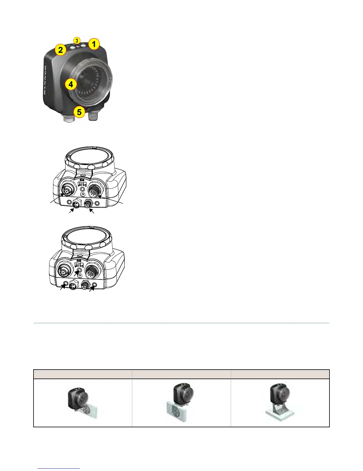
1 LED - Green: Ready; Red: Error
2 LED - Green: Pass; Red: Fail
3 Ethernet I/O LED
4 Focusing Window
5 Focusing Window Locking Clip
A Remote Display connector
B Power and I/O Cable connector
C USB connector
D Ethernet connector
Mounting Bracket Mounting Holes (uses supplied three M4 x 4 mm screws)
2.2 Installing and Connecting the Sensor
The iVu Plus TG sensor requires a bracket for mounting. Three brackets are available from Banner. The brackets allow the
sensor to be mounted either perpendicular to the part or at an adjustable angle.
Thread three M4 x 4mm screws through the bracket into the mounting holes in the bottom of the sensor. Tighten all three
screws.
Table 1: iVu Brackets
SMBIVURAL SMBIVURAR SMBIVUU
iVu Plus TG Gen2 Image Sensor
www.bannerengineering.com - Tel: 763.544.3164 7

 Loading...
