DECS-200 BESTCOMS Software 5-31
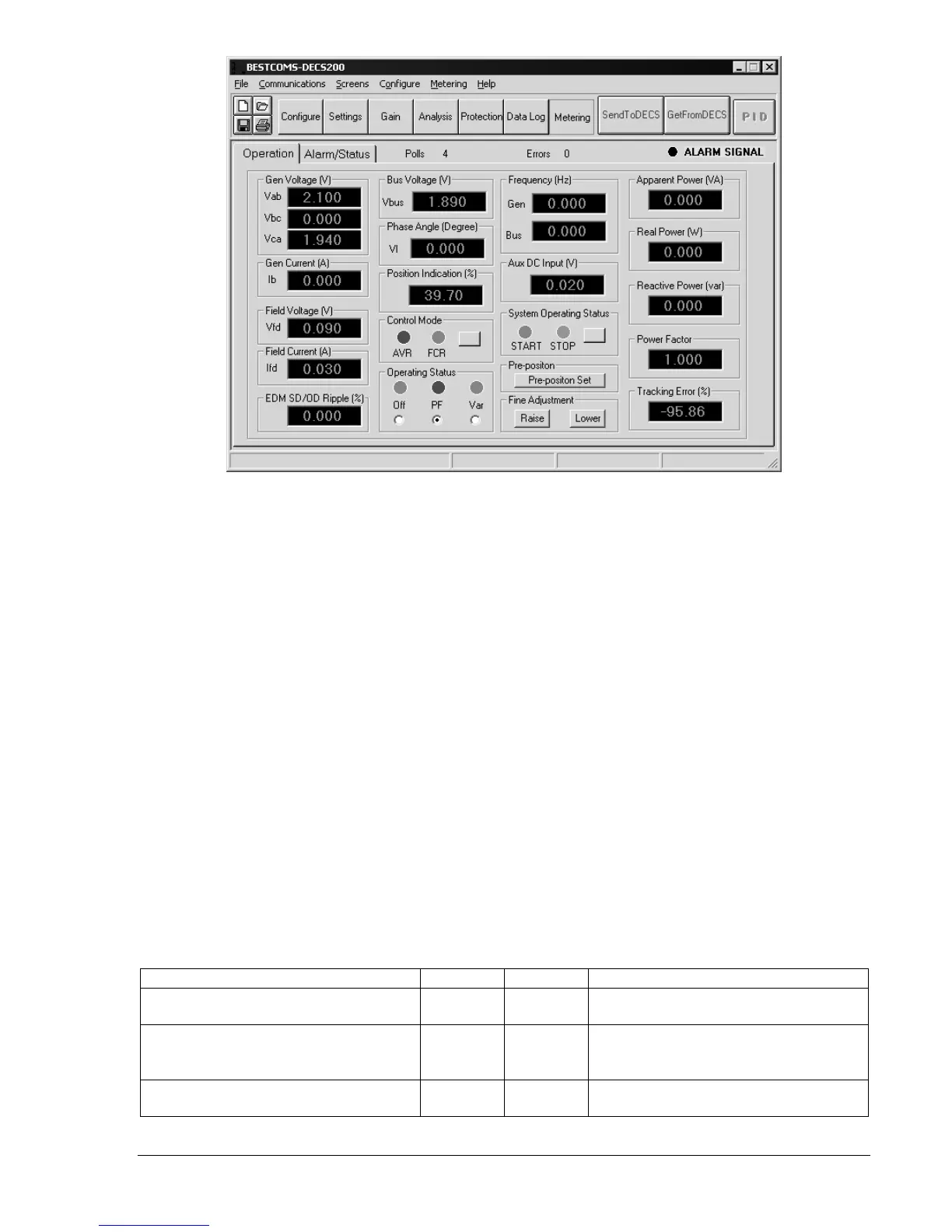
Figure 5-34. Metering Screen, Operation Tab
Frequency.
Displays the frequency of the generator voltage and bus voltage.
Aux DC Input.
Displays a value of voltage that is relative to the accessory input voltage or current,
depending on the mode selected.
Apparent Power.
Displays the apparent power, in VA, being supplied by the generator.
Real Power.
Displays the real power, in watts, being supplied by the generator.
Reactive Power.
Displays the reactive power, in vars, being supplied by the generator.
Power Factor.
Displays the operating power factor of the generator.
Tracking Error.
Displays the ratio, expressed as a percentage, of the nominal value of the tracking mode
to the mode being tracked. For example, if operating in AVR mode with 100 Vac nominal generator
voltage and a tracking error of –0.5%, a transfer to another operating mode would cause a decrease in
generator output voltage to 99.5 Vac.
Control Mode.
AVR and FCR mode status is reported by two indicators. When the DECS-200 is operating
in AVR mode, the AVR indicator changes from gray to red. When operating in FCR mode, the FCR
indicator changes from gray to green. A button is provided to toggle between AVR and FCR modes.
Operating Status.
Three indicators report whether Var mode is active, Power Factor mode is active, or
neither mode is active. An option button below each indicator is used to select the corresponding
operating mode. When Var mode is active, the Var indicator changes from gray to green. When Power
Factor mode is active, the PF indicator changes from gray to red. When neither mode is active, the Off
indicator changes from gray to blue. If the control mode is FCR and Var of PF mode is selected, that
selection will be ignored by the DECS-200. Even if the Var or PF indicator turns on, the system will not be
in those modes unless the DECS-200 52J/K input is open. See Table 5-3 for additional information on
52J/K and 52L/M logic.
Table 5-3. 52J/K and 52L/M Logic
DECS-200 Operating Mode 52 L/M 52 J/K Generator Operating Mode
AVR mode active, off-line OEL
enabled, no droop, no var/PF
Closed Closed Single unit/stand-alone
Droop mode active, on-line OEL
enabled, no var/PF
Open Closed Paralleled to the utility grid (droop) or
two or more generators islanded
(droop or cross-current compensation)
Var/PF mode active, on-line OEL
enabled
Open Open Paralleled to utility grid
NOTE: If neither var or power factor modes are selected via the operator interfaces, then the operating mode is
droop.