DECS-200 Functional Description 3-1
SECTION 3 • FUNCTIONAL DESCRIPTION
INTRODUCTION
This section illustrates and describes the functional capabilities of the DECS-200.
FUNCTION BLOCK DESCRIPTIONS
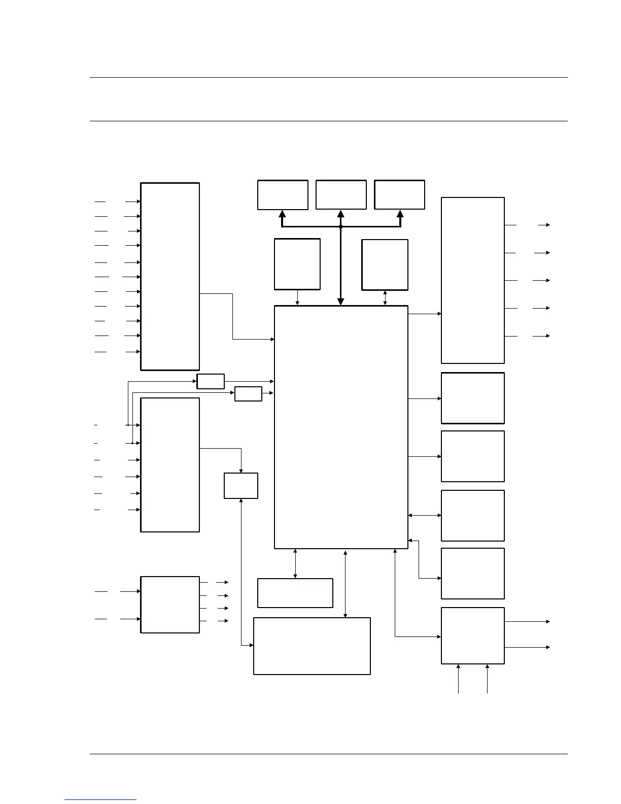
The function blocks of the DECS-200 are illustrated in Figure 3-1 and described in the following
paragraphs.
CONTACT
INPUT
CIRCUITS
POWER
SUPPLY
VAC
VDC
+5
+12
-12
+24
DIGITAL
SIGNAL
PROCESSOR
MICRO
PROCESSOR
FRONT
PANEL
LEDS
FRONT
PANEL
KEYPAD
FRONT
PANEL
LCD
ANALOG
INPUT
CIRCUITS
BUS
V
CA
GEN
V
CA
GEN
V
AB
LINE
I
B
LINE
I
A/C
ACC
V/I
ADC
RAM EEPROM
WATCH-DOG
TIMER
ZCD
ZCD
COM0
RS-232
PORT
COM1
RS-232
PORT
COM2
RS-485
PORT
P0003-19.vsd
03-09-01
FLASH
MEMORY
RELAY
OUTPUT
CONTACTS
ALRST
LOWER
RAISE
PRE-P
FCR
AUTO
CHOPPER
(PWM)
52J/K
POWER
INPUT
F+
F-
WTCHD
ON/OF
RLY3
RLY2
RLY1
START
52L/M
SECEN
STOP
Figure 3-1. Simplified Block Diagram