5-8 BESTCOMS Software DECS-200
Auxiliary Input, Auxiliary Gain Settings.
The four auxiliary gain setting fields, AVR, FCR, var, and PF,
select the gain which affects the setpoint of the selected operating mode. The signal applied to the
accessory input is multiplied by the auxiliary gain setting. Each gain setting can be adjusted from –99 to
+99 in increments of 0.01. For more information on the accessory gain settings, refer to Section 3,
Functional Description
.
Droop Settings, Reactive Droop Compensation.
Sets the level of droop compensation for paralleled
generators or line-drop compensations. Droop compensation is adjustable from 0 to +30% of the
generator nominal, terminal voltage in 0.1% increments. Line-drop compensation is adjustable from –30
to 0% of the generator nominal terminal voltage in 0.1% increments.
Droop Settings, Cross Current Compensation Gain.
Sets the level of cross-current compensation
(reactive differential) gain for paralleled generators. Cross-current compensation gain is adjustable from –
30 to +30% of the rated CTs in 0.01% steps. Refer to Section 4,
Installation
, for more information on
cross-current compensation gain.
Setting Adjustments
The Setting Adjustments screen consists of eight tabs labeled AVR/FCR, var/PF, Startup, OEL Type,
OEL (Summing), OEL (Takeover), UEL, and SCL. To view the setting adjustment screen, click the
Settings button on the tool bar or click S
creens on the menu bar and click Setting Adjustments.
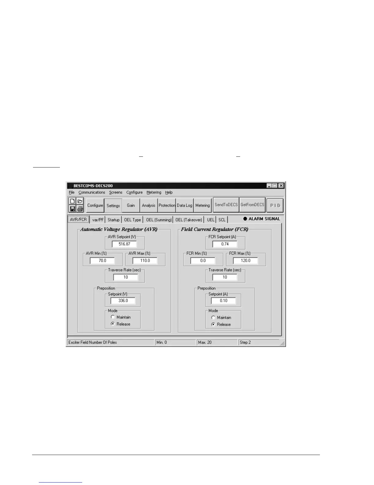
AVR/FCR
AVR/FCR tab functions are illustrated in Figure 5-12 and described in the following paragraphs.
Figure 5-12. Setting Adjustments Screen, AVR/FCR Tab
Automatic Voltage Regulator, AVR Setpoint.
Sets the desired generator output voltage when operating in
AVR mode. The range of this setting is based on the generator voltage setting entered on the Rated Data
tab of the System Configuration screen. This setting is also limited by the settings of the AVR Min and
AVR Max fields. If sensing step-down transformers are used, primary voltage should be entered.
Automatic Voltage Regulator, AVR Min.
Sets the minimum generator output voltage, expressed as a
percentage of the rated generator voltage. A setting of 70 to 100% may be entered in 0.1% increments.
Automatic Voltage Regulator, AVR Max.
Sets the maximum generator output voltage, expressed as a
percentage of the rated generator voltage. A setting of 70 to 100% may be entered in 0.1% increments.
Automatic Voltage Regulator, Traverse Rate (sec).
Determines the time required to adjust the AVR
setpoint from the minimum value to the maximum value of the adjustment range. A setting of 10 to 200
seconds may be entered in 1 second increments.