4-6 Installation DECS-200
CONNECTIONS
DECS-200 connections are dependent on the application and excitation scheme used. Observe the
following guidelines when making DECS-200 connections:
• A given application may not require the use of all DECS-200 inputs and outputs.
• Incorrect wiring may result in damage to the unit.
• Applying incorrect control power, operating power, or sensing values may damage the unit. Compare
the unit style number with the style chart (Figure 1-2) before applying control power.
Terminations for DECS-200 connections are located on the right-hand panel, the front panel, and the left-
hand panel.
Right-Hand Panel Connections
Right-hand panel terminations consist of a nine-pin, female, D-type connector (Com 1) that is used for
communication with a second DECS-200 unit when operating in a redundant system. A communication
cable, part number 9310300032, is available for interconnecting two DECS-200 units. Table 4-1 lists the
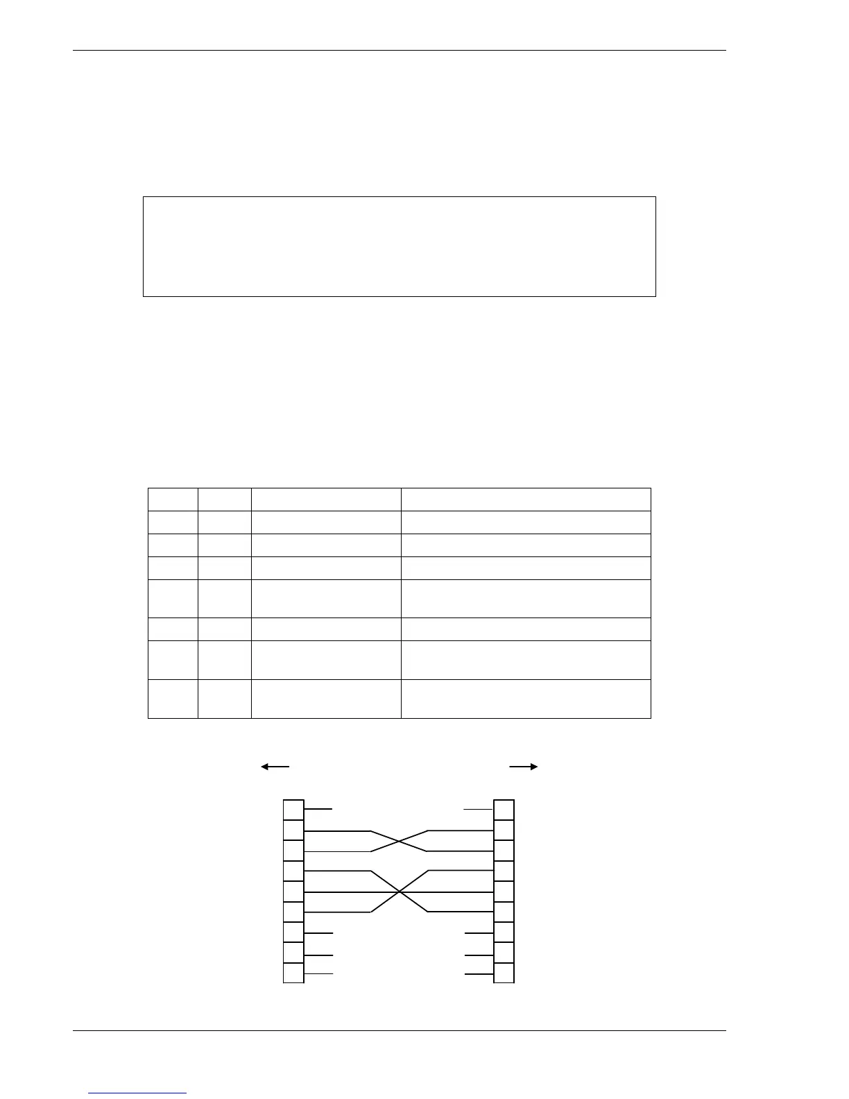
Com 1 pin numbers and functions. Figure 4-5 illustrates the communication connections between DECS-
200 units.
Table 4-1. Com 1 Pin Functions
Pin Name Description Function
1 Not used N/A
2 XMIT Transmit Sends serial data from DECS-200
3 RCV Receive Receives serial data from DECS-200
4 DTR Data Terminal Ready Receives signal indicating that the
sending unit is operational
5 GND Ground Provides the signal ground
6 DSR Data Set Ready Sends a signal indicating that the
DECS-200N is operational
7, 8,
9
Not used N/A
P0007-07
03-13-01
3
2
1
DB-9 MALE
TO DECS-200
DB-9 FEMALE
5
4
8
7
9
6
3
2
1
5
4
8
7
9
6
NO CONNECTION
NO CONNECTION
NO CONNECTION
NO CONNECTION
XMIT
RCV
DTR
GND
DSR
DB-9 MALE
TO DECS-200
DB-9 FEMALE
XMIT
RCV
DTR
GND
DSR
Figure 4-5. DECS-200 to DECS-200 Communication Connections
NOTE
The DECS-200 must be hard-wired to earth ground with no smaller than 12 AWG
copper wire attached to ground terminal C1. When the DECS-200 is configured
in a system with other devices, a separate lead should be used to connect each
device to the ground bus.