3-12 Functional Description DECS-200
In addition to the three current levels, the DECS-200 also uses embedded timers to prevent excessive
heating of the exciter field that may be a result of repetitive overexcitation conditions. A duration timer
monitors the accumulated time actually spent in an overexcitation condition and a reset timer is used to
count backward from either the High OEL Current Time setting or the sum of the high plus the Medium
OEL Current Time setting depending on the duration timer value. The reset timer countdown begins when
the excitation current falls below the low OEL current limit level. In the event a subsequent overexcitation
condition occurs before the reset timer reaches zero, the OEL limiter will resume from its state prior to the
excitation current falling below the low OEL current limit level. A full OEL cycle cannot occur until the reset
timer has counted down to zero after a previous OEL condition.
When the system is limiting overexcitation, an OEL condition is annunciated on the front panel Metering
screen and may be assigned to a programmable output relay for external annunciation.
Takeover OEL
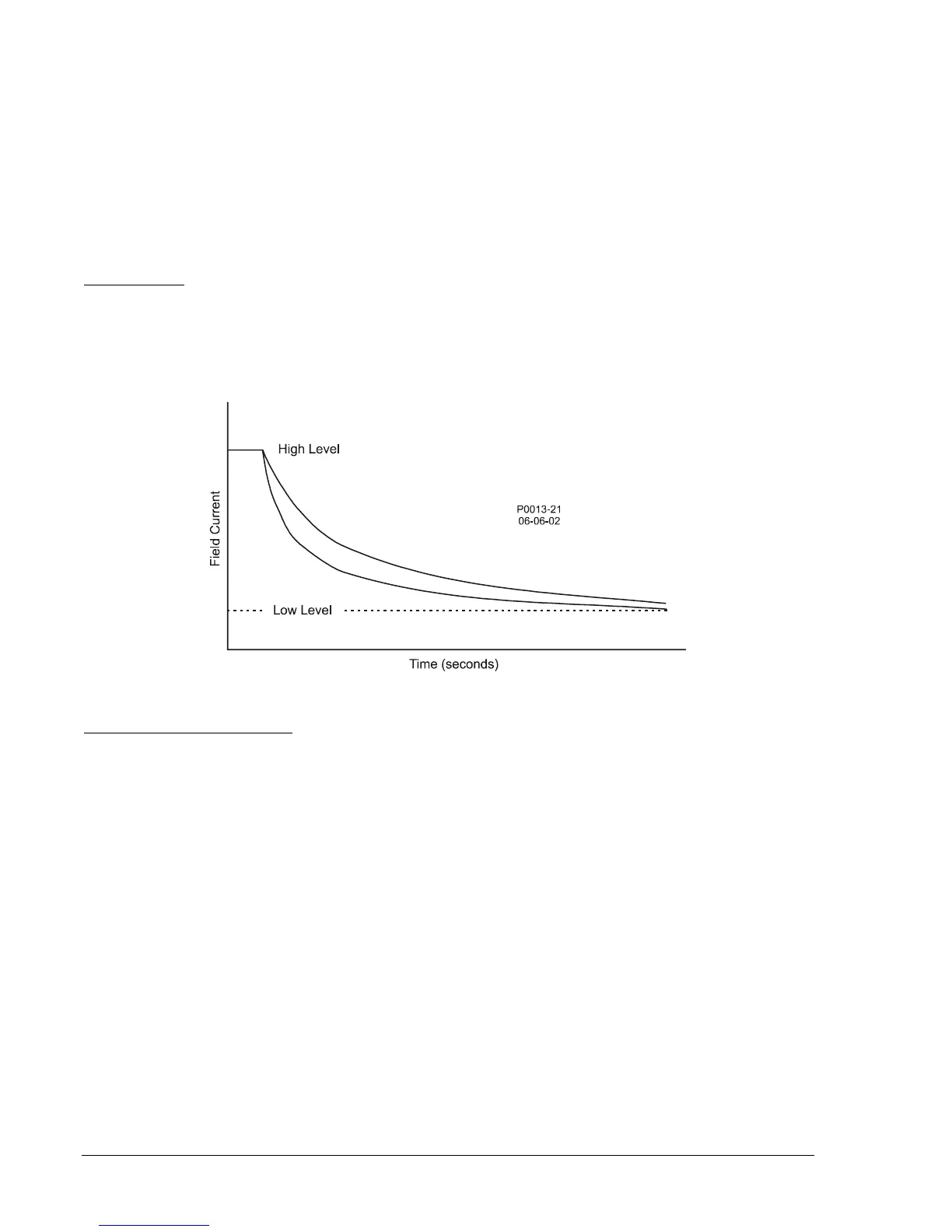
When takeover-style overexcitation limiting is used, the level of field current at which limiting occurs is
determined by an inverse time characteristic. This inverse time characteristic is similar to that shown in
Figure 3-8. Two current levels and a time dial setting are defined for the takeover OEL. Separate curves
may be selected for on-line operation. If the system enters an overexcitation condition, the field current is
limited and forced to follow the selected curve.
Figure 3-8. Inverse Time Characteristic for Takeover-Style OEL
On-Line/Off-Line OEL Options
Selection of on-line or off-line OEL levels/curves is determined by an OEL option selection. The following
options are available.
Option 1 (default). When option 1 is selected, on-line overexcitation limiter settings are active when either
the 52J/K contact input or 52L/M contact input are open. Off-line OEL settings are active when both the
52J/K contact input and 52L/M contact input are closed. The 52J/K contact input can be used to switch
between on-line OEL and off-line OEL when the 52L/M contact input is jumpered. If var/power factor
correction is disabled, Droop mode will be active when the 52J/K contact input is opened and AVR mode
will be active when the 52J/K contact input is closed.
Option 2. Option 2 allows the 52J/K contact input to define when the off-line and on-line limiters are
active. When option 2 is selected, on-line overexcitation limiter settings are active when the 52J/K contact
input is open. Off-line OEL settings are active when the 52J/K contact input is closed. Option 2 is
intended for cross-compound generator applications where both machines are paralleled at low rpm.
Therefore, Droop mode needs to be active (52L/M contact input opened) as the speed of the machines
are increased. However, off-line OEL settings for both machines need to be active.
Option 3. When option 3 is selected, on-line overexcitation limiting settings are active at all times. Option
3 allows the DECS-200 to operate in AVR mode (stand-alone application) without restriction from the off-
line OEL settings. In this case, the on-line OEL settings are active to limit excessive excitation current.
This option also eliminates the need for the DECS-200 to operate in Droop mode when applied in a single
unit application. Therefore, voltage should not droop as reactive load increases.