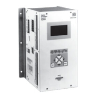
3-4 Functional Description DECS-200
Generator Voltage (V
AB
)
The GEN V
AB
input senses the generator voltage across phases A and B and is used to estimate the
generator rms voltage. This voltage is used with the V
CA
voltage to estimate the bus rms voltage and
frequency. This input is not internally isolated.
Bus Voltage (BUS V
CA
)
The BUS V
CA
input senses the bus voltage across phases A and C. This voltage is used to estimate the
bus rms voltage and frequency. The BUS V
CA
input is not internally isolated.
Phase B Line Current
This internally isolated input is developed from a current transformer (CT) and used to calculate the B-
phase generator line current.
Cross-Current Loop Input
This input is developed from a current transformer (CT) connected to phase B of a generator and used
when generators are operating in cross-current compensation mode.
Accessory Input (Remote Setpoint Control)
This internally isolated input may be either an analog voltage (–10 to +10 Vdc) or current (4 to 20
milliamperes). Separate terminals provide convenient terminations but only one input may be used in any
application. This input is typically supplied by a power system stabilizer or similar device.
The accessory voltage input signal changes the setpoint of the selected operating mode. This input may
be in the range of –10 to +10 Vdc or 4 to 20 milliamperes. The input signal is named a voltage signal
even though one input mode may be 4 to 20 milliamperes. When the current input mode is selected, the
input current (4 to 20 milliamperes) is converted by the DECS-200 to –5 to +5 Vdc voltage signal. The
following equation is used when converting current signals to voltage signals.
()
12625.0 −= IV
AUX
Where: V
AUX
is the voltage signal
I is the current in milliamperes
The accessory voltage input signal is multiplied by the accessory gain setting. The gain setting is in the
range of –99 to +99. If the gain is set to zero, the accessory voltage input signal is made inactive. The
accessory voltage input can be active in all four operating modes.
In AVR mode, the accessory voltage input signal is multiplied by the voltage gain setting which defines
the setpoint change as a percentage of the rated generator voltage.
In FCR mode, the accessory voltage input signal is multiplied by the current gain setting which defines the
setpoint change as a percentage of the rated field current.
In var mode, the accessory voltage input signal is multiplied by the var gain setting which defines the
setpoint change as a percentage of the rated apparent power of the generator.
In power factor mode, the accessory voltage input signal is multiplied by the power factor gain setting and
divided by 100 which defines the power factor setpoint change.
Field Current and Field Voltage
These signals are sensed internally. The field voltage signal is used for field overvoltage protection. The
field current signal is used for: off-line and on-line overexcitation limiting, auto-tracking, and field over-
current protection.
Operating Power
The DECS-200 operating power input accepts three-phase or single-phase voltage over the range of 50
to 277 Vac (depending on the nominal field voltage) at 50 to 500 hertz. The input is rectified and filtered
by the input’s low-pass filter, which feeds the chopper stage. Depending on the operating power applied,
three nominal output voltages are possible: 32, 63, or 125 Vdc.
Control Power
Control power may be either of two types:. nominal 24/48 Vdc or nominal 120 Vac/125 Vdc. For the 120
Vac/125 Vdc control power type, both ac and dc input power voltage may be applied for redundant power
supply operation. Refer to Section 1,
General Information, Specifications
, for voltage ranges. The power

 Loading...