5-30 BESTCOMS Software DECS-200
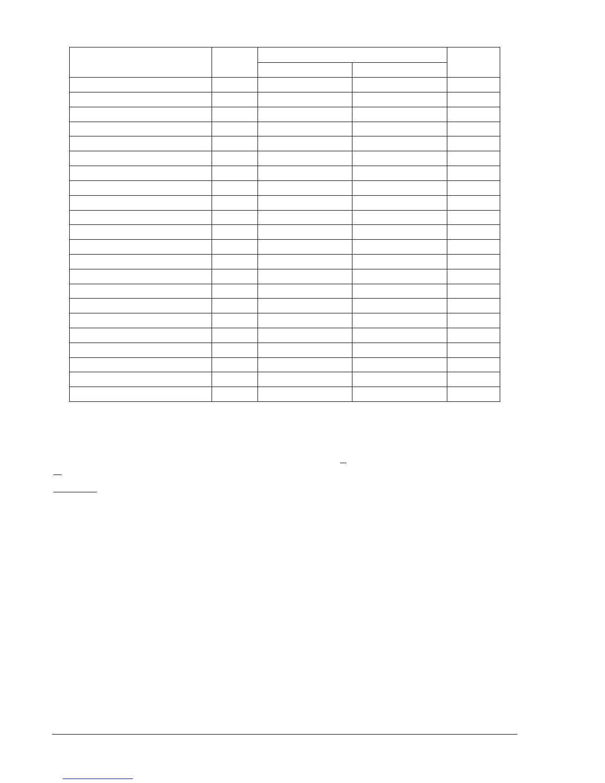
Table 5-2. Data Log Report Parameter Triggers
Threshold
Parameter
Unit of
Measure
Lower Upper
Increment
Auto Tracking Output N/A –65535 to 65535 –65535 to 65535 1
Auxiliary Input Voltage PU –2 to 2 –2 to 2 0.01
Average Gen. Voltage, L-L PU –2 to 2 –2 to 2 0.01
AVR Error Signal N/A –65535 to 65535 –65535 to 65535 1
Bus Frequency Hz 0 to 90 0 to 90 0.01
Bus Voltage PU –2 to 2 –2 to 2 0.01
Control Output N/A –65535 to 65535 –65535 to 65535 1
Cross-Current Input PU –2 to 2 –2 to 2 0.01
Field Current PU –2 to 2 –2 to 2 0.01
Field Voltage PU –2 to 2 –2 to 2 0.01
Gen. Apparent Power kVA PU –2 to 2 –2 to 2 0.01
Gen. Reactive Power kvar PU –2 to 2 –2 to 2 0.01
Gen. Real Power kW PU –2 to 2 –2 to 2 0.01
Generator Current Ib PU –2 to 2 –2 to 2 0.01
Generator Frequency Hz 0 to 90 0 to 90 0.01
Generator Power Factor PF –1 to 1 –1 to 1 0.01
Generator Voltage Vab PU –2 to 2 –2 to 2 0.01
Generator Voltage Vbc PU –2 to 2 –2 to 2 0.01
Generator Voltage Vca PU –2 to 2 –2 to 2 0.01
Phase Angle, V-I Degrees –180 to 180 –180 to 180 0.01
PID Integrator State N/A –65535 to 65535 –65535 to 65535 1
Var/PF Controller Output N/A –65535 to 65535 –65535 to 65535 1
Metering
The Metering screen consists of two tabs labeled Operation and Alarm/Status. To view the Metering
screen, click the Metering button on the tool bar or click S
creens on the menu bar and click
M
etering/Operation.
Operation
Operation tab parameters and controls are illustrated in Figure 5-34 and described in the following
paragraphs.
DECS-200 BESTCOMS software provides real-time monitoring of the following data. This data is
refreshed approximately once every second. Metering is enabled or disabled through the pull-down menu
or by clicking the Metering button.
Real-time metering values on the Operation tab are refreshed approximately once per second. Metering
is enabled or disabled through the Metering menu on the menu bar or by clicking the Metering button.
Gen Voltage.
Displays three values of generator voltage: Vab, Vbc, and Vca.
Gen Current.
Displays phase B generator current.
Field Voltage.
Displays the level of field voltage.
Field Current.
Displays the level of field current.
EDM SD/OD Ripple.
Displays the percentage of ripple detected across the exciter diodes by the exciter
diode monitor.
Bus Voltage.
Displays the level of bus voltage.
Phase Angle.
Displays the phase angle between the generator voltage and current.
Position Indication.
Displays the relative position (in percent) of the current setpoint value to the
programmed minimum or maximum setpoint.