DECS-200 Modbus™ Communication 7-3
Message Framing and Timing Considerations
When receiving a message, the DECS-200 requires an inter-byte latency of 3.5 character times before
considering the message complete.
Once a valid query is received, the DECS-200 waits a specified amount of time as specified in the
Modbus Response Delay Time Register (48108) before responding. This Register contains a value from
0 to 200 milliseconds. The default value is 10 milliseconds. The user may set the remote delay time
parameter to 0 to minimize response latency.
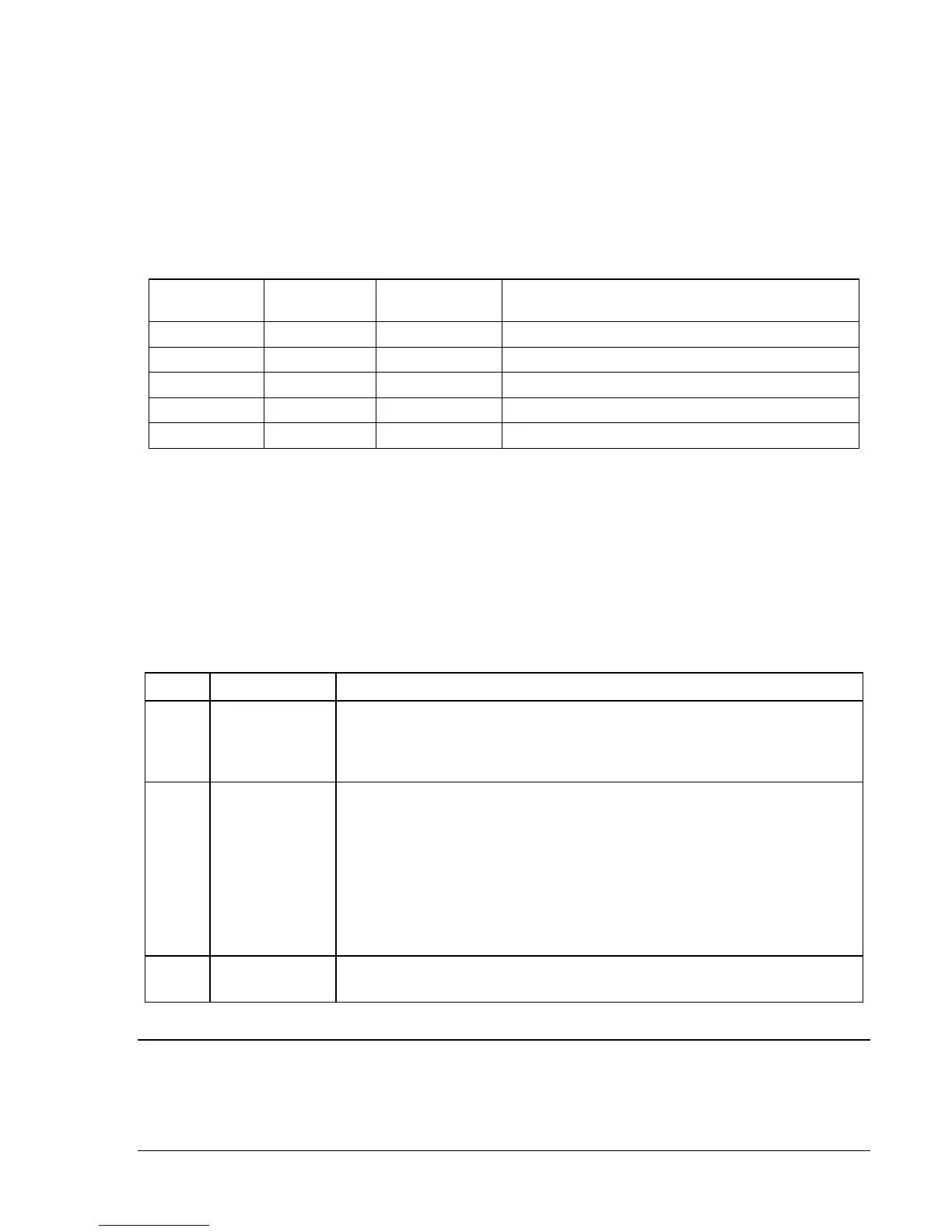
Table 7-2 provides the response message transmission time (in milliseconds) and 3.5 character times (in
milliseconds) for the maximum response message length (225 characters), response to a read query for
125 points and various baud rates.
Table 7-2. Timing Considerations For 10 Character Bits (8 Data Bits + 1 Start Bit + 1 Stop Bit)
Baud Rate
1 Character
Time (ms)
3.5 Characters
Time (ms)
Max. Read Register Response Message
(255 characters) Transmission Time (ms)
1,200 8.33 29.17 2,124.15
2,400 4.17 14.58 1,063.35
4,800 2.083 7.292 531.165
9,600 1.0417 3.645 265.6335
19,200 0.52083 1.823 132.812
Error Handling and Exception Responses
Any query received that contains a nonexistent device address, a framing error, or CRC error is ignored.
No response is transmitted. Queries addressed to a DECS-200 with an unsupported function code,
unsupported register references or illegal values in the data block result in an error response message
with an exception response code.
Each error response message consists of a slave (DECS-200) address, function code with the high order
bit set, error code and error check (CRC) field.
The exception response error codes supported by the DECS-200 are provided in Table 7-3.
Table 7-3. Supported Exception Response Codes
Code Name Meaning
01 Illegal Function
The query Function/Sub-function Code is unsupported; query read of more
than 125 registers; query “preset multiple registers” of more than 100
registers
02
Illegal Data
Address
A register referenced in the data block does not support queried read/write;
For Function Codes 3 and 16 additionally:
1. Starting Register address is mapped to DECS-200 Modbus address
space but is not referenced to the highest order 16 bits of the assigned
application data (see explanation in 2.7 Data Formats), and
2. The number of registers is too small to hold entire value of all data
(variables) assigned to those registers (see explanation in 2.7 Data
Formats).
03
Illegal Data
Value
A preset register data block contains an incorrect number of bytes or one or
more data values out of range.
COMMUNICATIONS HARDWARE REQUIREMENTS
The DECS-200 RS-485 physical interface consists of three positions of a terminal strip with locations for
Send/Receive A (A), Send/Receive B (B) and Signal Ground (C).