4-10 Installation DECS-200
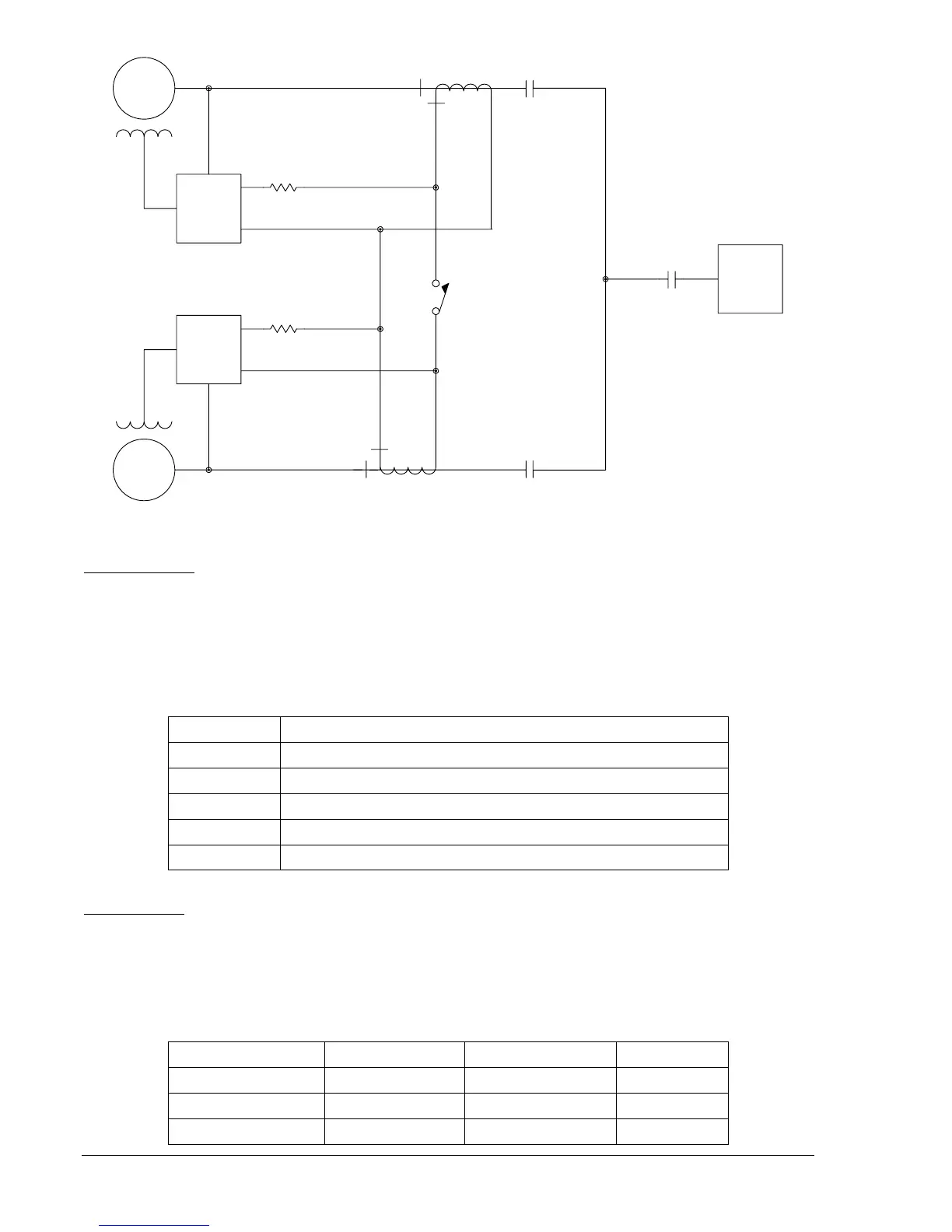
GEN 1
GEN 2
CT CC 5A
CT CC COM
DECS-200
CT CC 5A
CT CC COM
DECS-200
1.0
1.0
CT
CT
LOAD
CCC
ENABLE
CONTACT
05-28-04
P0005-02
Phase B
Phase B
Figure 4-7. Typical Cross-Current Compensation Connections
Accessory Input
DECS-200 units accept analog accessory signals from other controllers (e.g., power system stabilizers)
for remote control of the setpoint. Two types of accessory inputs are provided: voltage and current. Only
one accessory input (voltage or current) may be used at one time. The voltage input accepts a signal over
the range of –10 Vdc to +10 Vdc. The current input accepts a signal over the range of 4 mAdc to 20
mAdc. Shielded cable is recommended for the accessory signal. Terminal A8 is provided for the shield
connection. Accessory input terminal assignments are listed in Table 4-7.
Table 4-7. Accessory Input Terminals
Terminal Description
A6 (I+) Positive side of current accessory input
A7 (I–) Negative side of current accessory input
A8 (GND) Shield connection for accessory input
A9 (V+) Positive side of voltage accessory input
A10 (V–) Negative side of voltage accessory input
Contact Inputs
The DECS-200 has 11 fixed-function contact inputs. Each contact input supplies an interrogation voltage
of 12 Vdc and accepts dry switch/relay contacts or open-collector PLC outputs. Open-collector devices
connected to the contact inputs must be compatible with the 12 Vdc interrogation voltage, be capable of
conducting a minimum of 5 mAdc, and have off-state leakage current no greater than 100 μAdc. Table 4-
8 lists the contact input terminals.
Table 4-8. Contact Input Terminals
Function Terminal Common Terminal Input Type
Start A21 (START) A22 (COM) Momentary
Stop A23 (STOP) A24 (COM Momentary
AVR Mode Enable A25 (AUTO) A26 (COM) Momentary