DECS-200 Installation 4-11
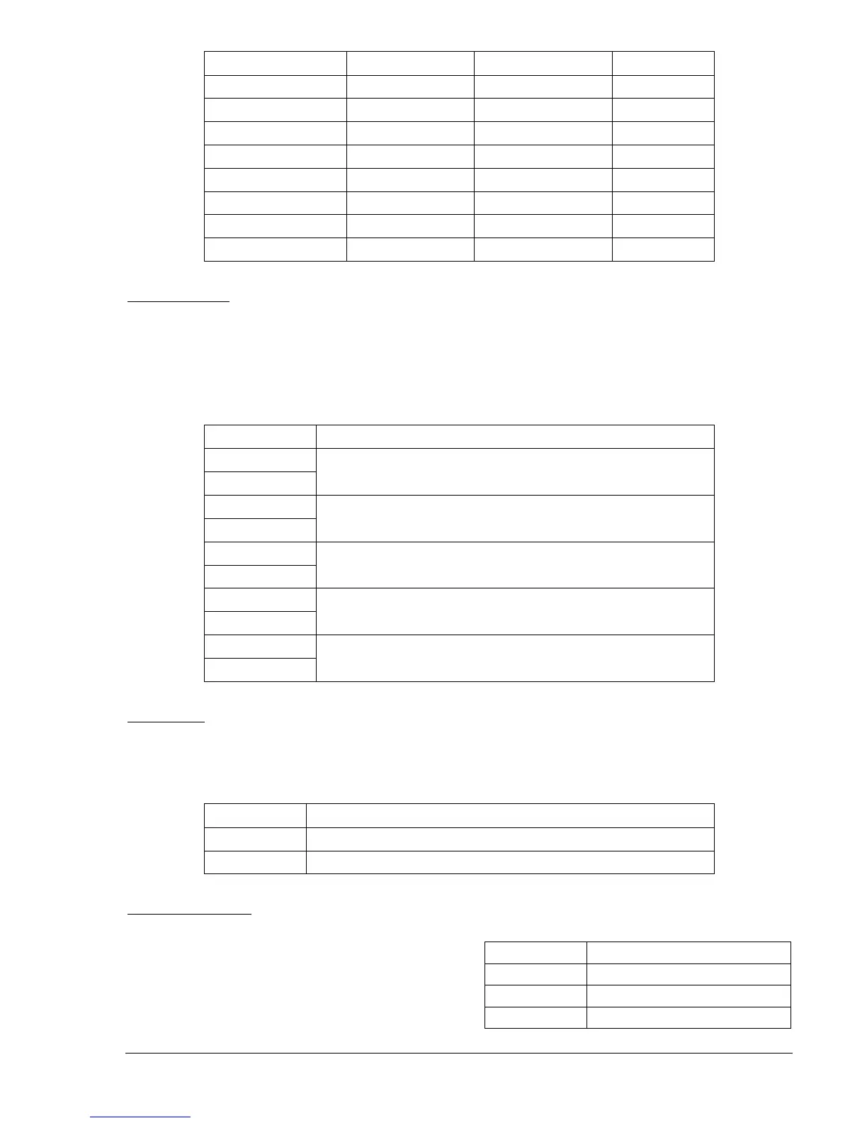
Function Terminal Common Terminal Input Type
FCR Mode Enable A27 (FCR) A28 (COM) Momentary
Raise Command A29 (RAISE) A30 (COM) Momentary
Lower Command A31 (LOWER) A32 (COM) Momentary
Pre-Position A33 (PRE-P) A34 (COM) Continuous
Unit/Parallel A35 (52L/M) A36 (COM) Continuous
Var/PF Enable A37 (52J/K) A38 (COM) Continuous
Secondary Enable A39 (SECEN) A40 (COM) Continuous
Alarm Reset A41 (ALRST) A42 (COM) Momentary
Output Contacts
The DECS-200 has two fixed-function contact outputs and three user-programmable contact outputs. All
output contacts are normally open (NO) except for the Watchdog output which is normally closed (NC).
Output contact terminal assignments are listed in Table 4-9. For additional information about relay output
specifications, refer to Section 1,
General Information
. For information about configuring the user-
programmable outputs, refer to Section 3,
Functional Description
.
Table 4-9. Output Contact Terminals
Terminal Description
A11 (ON/OF)
A12 (ON/OF)
On/Off contact terminals
A13 (WTCHD)
A14 (WTCHD)
Watchdog contact terminals (normally closed)
A15 (RLY1)
A16 (RLY1)
Programmable relay #1 terminals
A17 (RLY2)
A18 (RLY2)
Programmable relay #2 terminals
A19 (RLY3)
A20 (RLY3)
Programmable relay #3 terminals
Field Output
The DECS-200 output is capable of supplying 15 Adc of continuous excitation current to a field with no
less than 2.13 ohms of resistance (at 32 Vdc), 4.2 ohms of resistance (at 63 Vdc), or 8.3 ohms of
resistance (at 125 Vdc). Field output terminals are listed in Table 4-10.
Table 4-10. Field Output Terminals
Terminal Description
C5 (F+) Field output positive terminal
C6 (F–) Field output negative terminal
Com 2 Connections
Communication port Com 2 is intended for
polled communication over a Modbus network.
Twisted-pair cable is recommended for Com 2
connections. Com 2 terminals are listed in Table
4-11. Figure 4-8 illustrates the Com 2
connections used for multiple DECS-200 units
communicating over a Modbus network.
Table 4-11. Com 2 Terminals
Terminal Description
A43 (A) RS-485 send/receive A terminal
A44 (B) RS-485 send/receive B terminal
A45 (C) RS-485 signal ground terminal