Modbus™ Communication DECS-200
7-2
Modbus protocol limits a device address from 1 to 247. The address is user-selectable at installation, and
can be altered during real-time operation.
Function Code Field
The function code field in the query message defines the action to be taken by the addressed slave. This
field is echoed in the response message and is altered by setting the most significant bit (MSB) of the
field to 1 if the response is an error response. This field is 1 byte.
The DECS-200 maps all registers into the Modicon
TM
984 holding register address space (4XXXX) and
supports the following function codes:
- READ OUTPUT REGISTERS (function code 3),
- PRESET SINGLE REGISTER WRITE (function code 6)
- PRESET MULTIPLE REGISTERS (function code 16), and
- LOOPBACK DIAGNOSTIC TEST (function code 8) with diagnostic sub-functions:
- Return Query Data (diagnostic code 0),
- Restart Comm. option (diagnostic code 1), and
- Force Slave To Listen Only Mode (LOM, diagnostic code 4).
DECS-200 Modbus performs all of the above functions when a Modbus message has its unique address
which is numbered from 1 to 247. DECS-200 also recognizes a broadcast (group) address of 0. Only
functions 16 and 8 are recognized as valid for broadcast. The DECS-200 does not send a response
message for a broadcast query.
In listen-only mode (LOM), received data is monitored (but no responses are transmitted). The only query
that will be recognized and processed while in LOM is a maintenance restart command (function code 8,
diagnostic code 1).
Data Block Field
The query data block contains additional information needed by the slave to perform the requested
function. The response data block contains data collected by the slave for the queried function. An error
response will substitute an exception response code for the data block. The length of this field varies with
each query. See the paragraphs on
Register Definitions
in this manual for interpretation of register data.
Error Check Field
The error check field provides a method for the slave to validate the integrity of the query message
contents and allows the master to confirm there validity. This field is 2 bytes.
SERIAL TRANSMISSION DETAILS
A standard Modbus network offers two transmission modes for communication: ASCII or Remote
Terminal Unit (RTU). The DECS-200 supports only the RTU mode via rear RS-485 serial interface.
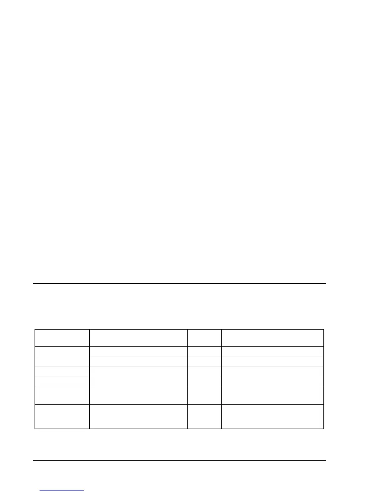
Communication settings for the DECS-200 Rear RS-485 port are listed in Table 7-1.
Table 7-1. DECS-200 Communication Settings
Setting Programmable Y(Yes) / N(No)
Default
Value
Value Range
Baud Rate Y 9600 1200/2400/4800/9600/19200
Data Size in Bits N 8 N/A
Parity Y None ‘N’=None, ‘O’=Odd, ‘E’=Even
Stop Bits Y 2 1 or 2
Modbus Slave
Address
Y 247 0 for broadcast, 1 to 247 for slave
Modbus
Response Delay
Time in ms
Y 10 ms
From 0 to 200 ms in increments of
10 ms
Communication settings are user-selectable and can be set at installation and altered during real-time
operation.