DECS-200 Functional Description 3-3
two or more generators paralleled together on an isolated bus (islanded) or paralleled directly to the utility
grid. Cross-current compensation (CCC) can also be utilized in this contact configuration. However, this
mode (CCC) is not intended for paralleling to the utility grid.
If both 52L/M is open and 52J/K are open, var/power factor mode is active while the on-line overexcitation
limiter is enabled and will limit if the settings are exceeded. This mode is intended for applications
requiring var or power factor regulation when paralleled to the utility grid.
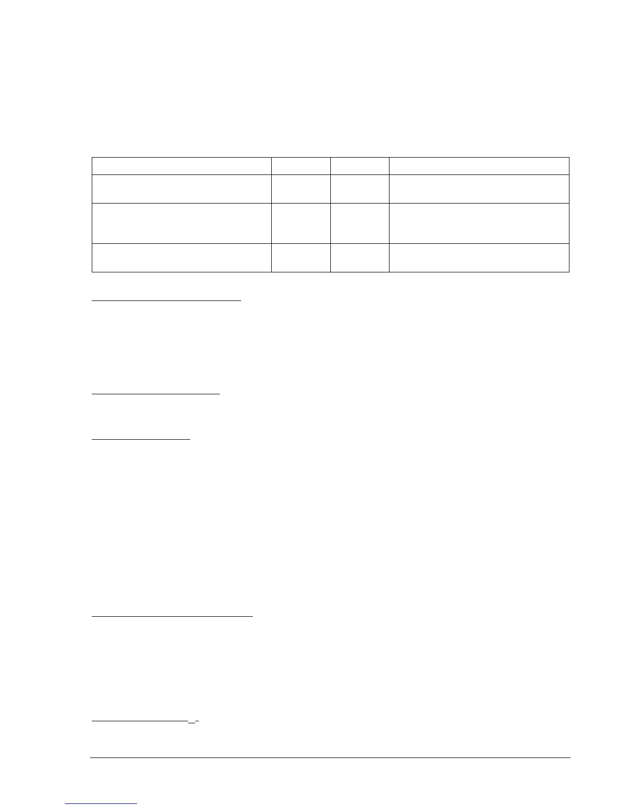
Table 3-1 describes 52 L/M and 52 J/K contact functionality for default OEL option 1. OEL options 2 and 3
are discussed in
Overexcitation Limiter, On-Line/Off-Line OEL Options
.
Table 3-1. 52L/M and 52J/K Truth Table (Option 1, Default Settings)
DECS-200 Operating Mode 52L/M 52J/K Generator Operating Mode
AVR mode active, off-line OEL
enabled, no droop, no var/PF
Closed Closed Single unit/stand-alone
Droop mode active, on-line OEL
enabled, no var/PF
Open Closed Paralleled to the utility grid (droop) or
two or more generators islanded
(droop or cross-current comp.)
Var/PF mode active, on-line OEL
enabled
Open Open Paralleled to utility grid
52J/K (Var/Power Factor Enable)
This input accepts a continuous contact closure that disables var/power factor operation. An open contact
enables the DECS-200 to control the generator reactive power in either the var or power factor modes.
These functions must be enabled via HMI, BESTCOMS or Modbus before use. For more information,
refer to the
52L/M (Unit/Parallel)
paragraphs. If neither var nor power factor mode is desired, it is
recommended that a jumper wire be placed across the 52J/K and common terminals, and switch the
52L/M input with the generator breaker auxiliary contact (52b).
SECEN (Secondary Enable)
This input accepts a continuous contact closure and enables the DECS-200 unit as the secondary unit to
another excitation control system.
ALRST (Alarm Reset)
This input accepts a momentary contact closure to clear all latched relay annunciations and front panel
alarm messages.
Analog Inputs
The following analog inputs are used to sense the following quantities:
• Generator voltage (three-phase/single-phase)
• Bus voltage (single-phase)
• Phase B (line) current
• Cross current loop input
• Accessory input (remote setpoint control)
• Field voltage (internal)
• Field current (internal)
Generator Voltage Sensing Ranges
The ac voltage sensing range of the DECS-200 is split into four operating ranges: 120 volts nominal, 240
volts nominal, 480 volts nominal, and 600 volts nominal. The range selection is the same for generator
and bus voltages and is based on the secondary VT voltage for the generator voltage sensing. The 120
volt range is selected if the generator secondary VT voltage is between 85 and 153 Vac. The 240 volts
range is selected if the generator secondary VT voltage is between 170 and 300 Vac. The 480 volt range
is selected if the generator secondary VT voltage is between 340 and 528 Vac. The 600 volt range is
selected if the generator VT voltage is between 540 and 690 Vac.
Generator Voltage (V
CA
)
The GEN V
CA
input senses the generator voltage across phases A and C. This voltage is used to estimate
the generator rms voltage and frequency.