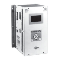
3-6 Functional Description DECS-200
o Field overvoltage
o Field overcurrent
o Generator undervoltage
o Generator overvoltage
o Volts per hertz or underfrequency limit
o Overexcitation limit
o Underexcitation limit
o FCR mode
o Loss of sensing (LOS) voltage
o Active setpoint at low limit
o Active setpoint at high limit
o Generator frequency below 10 hertz
o Open exciter diode
o Shorted exciter diode
o Loss of field
o Stator current limit
Watchdog Output
The Watchdog (WTCHD) output indicates a software execution problem within the DECS-200. The
contact closes under the following circumstances:
• No control power is applied to the DECS-200
• After application of power for approximately eight seconds
• Software in the DECS-200 stops executing normally
On/Off Output
The On/Off (ON/OF) output indicates the enabled/disabled status of the DECS-200. the On/Off output
closes when the DECS-200 is enabled and opens when the DECS-200 is disabled.
Communication
The RS-232 port (Com 0), located on the front panel, is dedicated for communication with a PC running
BESTCOMS software.
The RS-232 port (Com 1), located on the right side of the unit, is dedicated for communication with a
second DECS-200. This port provides tracking between units in a redundant DECS-200 system.
The RS-485 Port (Com 2), located on the left side of the unit, is dedicated for communication in remote
terminal unit (RTU) mode using the Modbus protocol.
All three ports have a default baud rate of 9600. However, the baud rate for each port can be set
independently. Available baud rates are 1200, 2400, 4800, 9600, and 19200. Ports Com ) and Com 1 use
a data format of 8N1 which stands for 8 data bits, no parity, and 1 stop bit. Port Com 2 has a default data
format of 8N2 but the parity and number of stop bits are programmable. The choices for parity include:
None, Odd, and Even. The number of stop bits may be either 1 or 2.
Memory Circuits
There are three types of memory circuits: flash memory, random access memory (RAM) and electrically
erasable programmable read-only memory (EEPROM). Flash memory is nonvolatile and stores the
NOTE
If the contacts of a programmable output relay are configured as normally closed,
the normally closed contact state is maintained only while the DECS-200 has
control power applied. When power is removed from the DECS-200, these
contacts will open.
NOTE
Changing the baud rate or data format while that interface is in use will result in a
loss of data and probably a complete loss of communication.

 Loading...