DECS-200 BESTCOMS Software 5-7
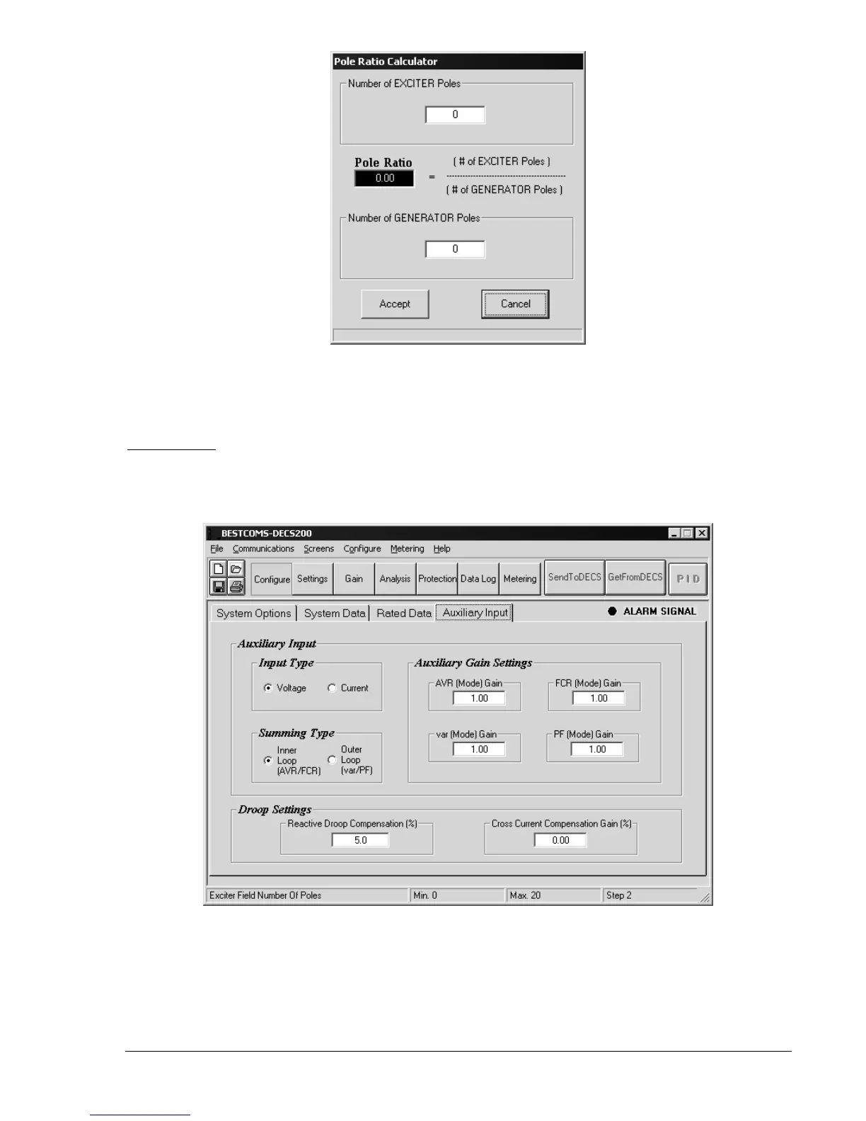
Figure 5-10. Pole Ratio Calculator
Pole Ratio, Pole Ratio.
Sets the ratio of the number of exciter poles to the number of generator poles. A
setting of 0 to 10 may be entered in 0.01 increments. This value can be calculated automatically using the
pole ratio calculator , accessed by clicking the Calculate Pole Ratio button.
Auxiliary Input
The auxiliary voltage input signal changes the setpoint of the selected operating mode. For more
information on the auxiliary voltage input, refer to Section 3,
Functional Description
. Auxiliary Input tab
functions are shown in Figure 5-11 and described in the following paragraphs.
Figure 5-11. System Configuration Screen, Auxiliary Input Tab
Auxiliary Input, Input Type.
Selects the accessory input type as voltage or current for remote control of the
setpoint.
Auxiliary Input, Summing Type.
Selects either Inner Loop or Outer Loop as the summing type. When
Inner Loop is selected, the operating mode is either AVR of FCR. When Outer Loop is selected, the
operating mode is either var or power factor.