DECS-200 Setup 6-3
Enter the generator CT secondary current rating ......................................................................... ________
Enter the bus PT primary voltage rating (if applicable)................................................................. ________
Enter the bus PT secondary voltage rating (if applicable) ............................................................ ________
Enable or disable internal tracking................................................................................................ ________
Set the internal tracking delay (1 second is suggested) ............................................................... ________
Set the internal tracking traverse rate (10 seconds is suggested)................................................ ________
Enable or disable external tracking (applies only to redundant DECS-200 systems) .................. ________
Set the external tracking delay (applies only to redundant DECS-200 systems) ......................... ________
Set the external tracking traverse rate (applies only to redundant DECS-200 systems) ............. ________
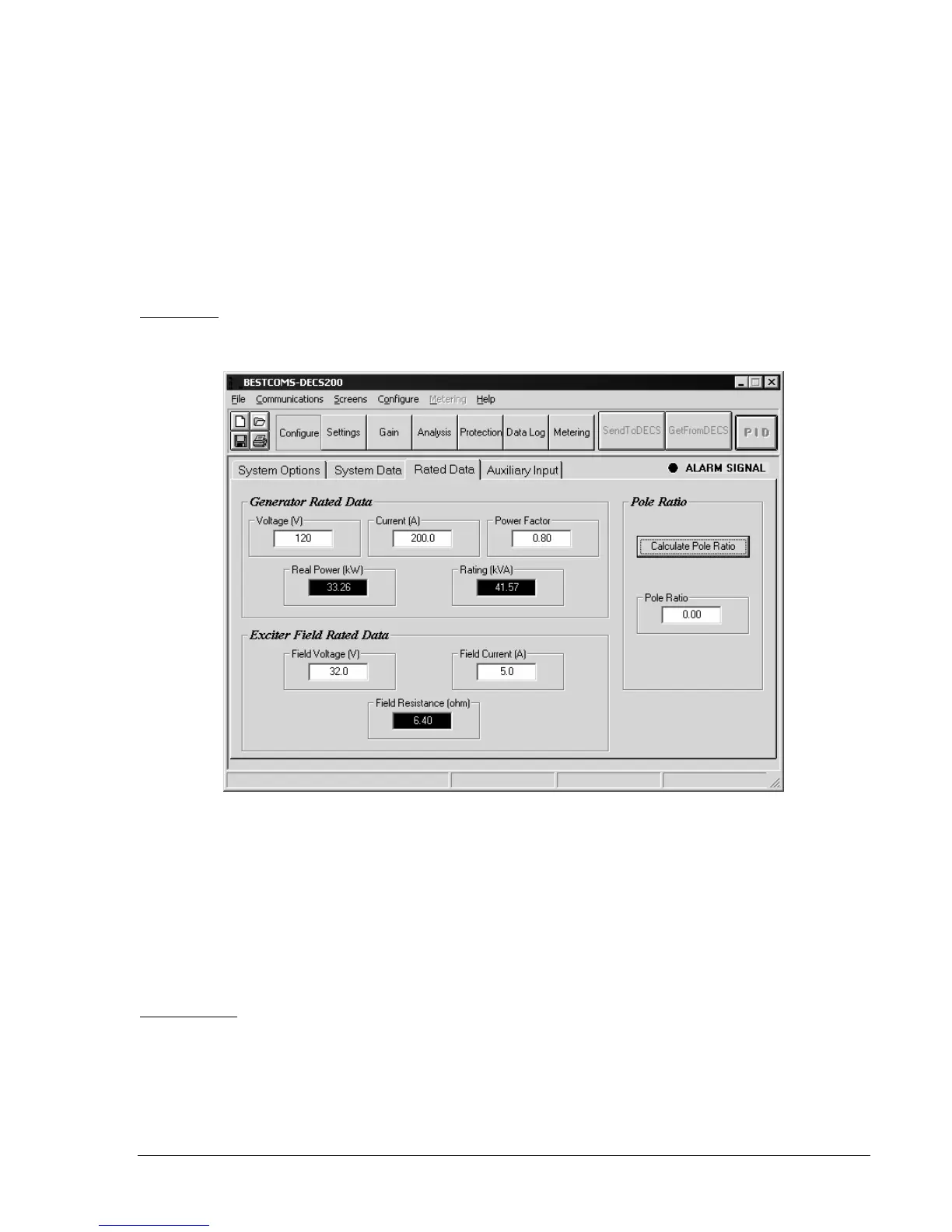
Rated Data
Enter the generator and exciter field ratings and exciter-to-generator pole ratio settings illustrated in
Figure 6-3.
Figure 6-3. Rated Data Tab
Enter the rated generator terminal voltage ................................................................................... ________
Enter the rated generator current ................................................................................................. ________
Enter the rated generator power factor......................................................................................... ________
Enter the exciter-to-generator pole ratio ....................................................................................... ________
Enter the rated exciter field voltage ............................................................................................. ________
Enter the rated exciter field current............................................................................................... ________
Auxiliary Input
Configure the accessory input selections and settings illustrated in Figure 6-4.
Select either voltage or current as the accessory input type ........................................................ ________
Select either inner loop (AVR/FCR) or outer loop (var/PF) as the summing type ........................ ________
Enter the accessory input gain (multiplier) setting for AVR mode ................................................ ________
Enter the accessory input gain (multiplier) setting for FCR mode ................................................ ________