DECS-200 Setup 6-11
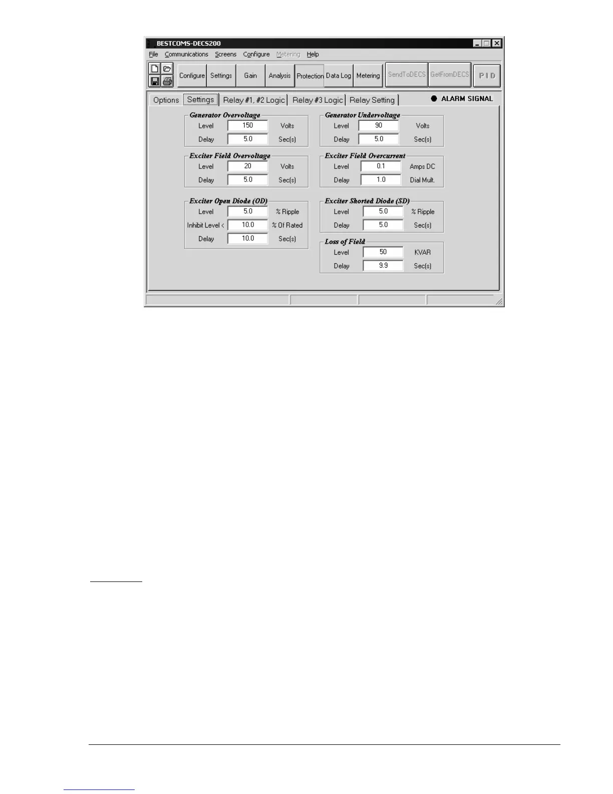
Figure 6-14. Protection Settings Tab
Enter the threshold for field overvoltage protection ...................................................................... ________
Enter the time delay for field overvoltage protection..................................................................... ________
Enter the percent of rated field current that indicates an open exciter diode ............................... ________
Enter the percent of rated field current that disables open- and shorted-diode protection .......... ________
Enter the annunciation time delay for open exciter diode protection............................................ ________
Enter the threshold for generator undervoltage protection ........................................................... ________
Enter the time delay for generator undervoltage protection ......................................................... ________
Enter the threshold for field overcurrent protection ...................................................................... ________
Enter the time delay for field overcurrent protection ..................................................................... ________
Enter the percent of rated field current that indicates a shorted exciter diode ............................. ________
Enter the annunciation time delay for shorted exciter diode protection........................................ ________
Enter the threshold for loss of field protection .............................................................................. ________
Enter the time delay for loss of field protection............................................................................. ________
Relay Logic
Review the excitation system interconnection drawings and verify the relay configurations. Relay logic
settings for each of the three DECS-200 programmable outputs are contained on two tabs with identical
configuration options. Only the tab for Relays 1 and 2 is illustrated here (Figure 6-15). Table 6-2 lists all of
the available functions that can be assigned to the programmable outputs. Checkmarks may be placed in
Table 6-2 to identify the functions assigned to each relay output.