DECS-200 Setup 6-15
Generator output voltage should build to a percentage of the rated voltage. (The FCR setpoint was set at
20% of the no-load excitation current in a previous step.)............................................................ ________
Increase the exciter field rated current to 75% of current............................................................. ________
The generator output voltage should build to a percentage of the rated voltage ......................... ________
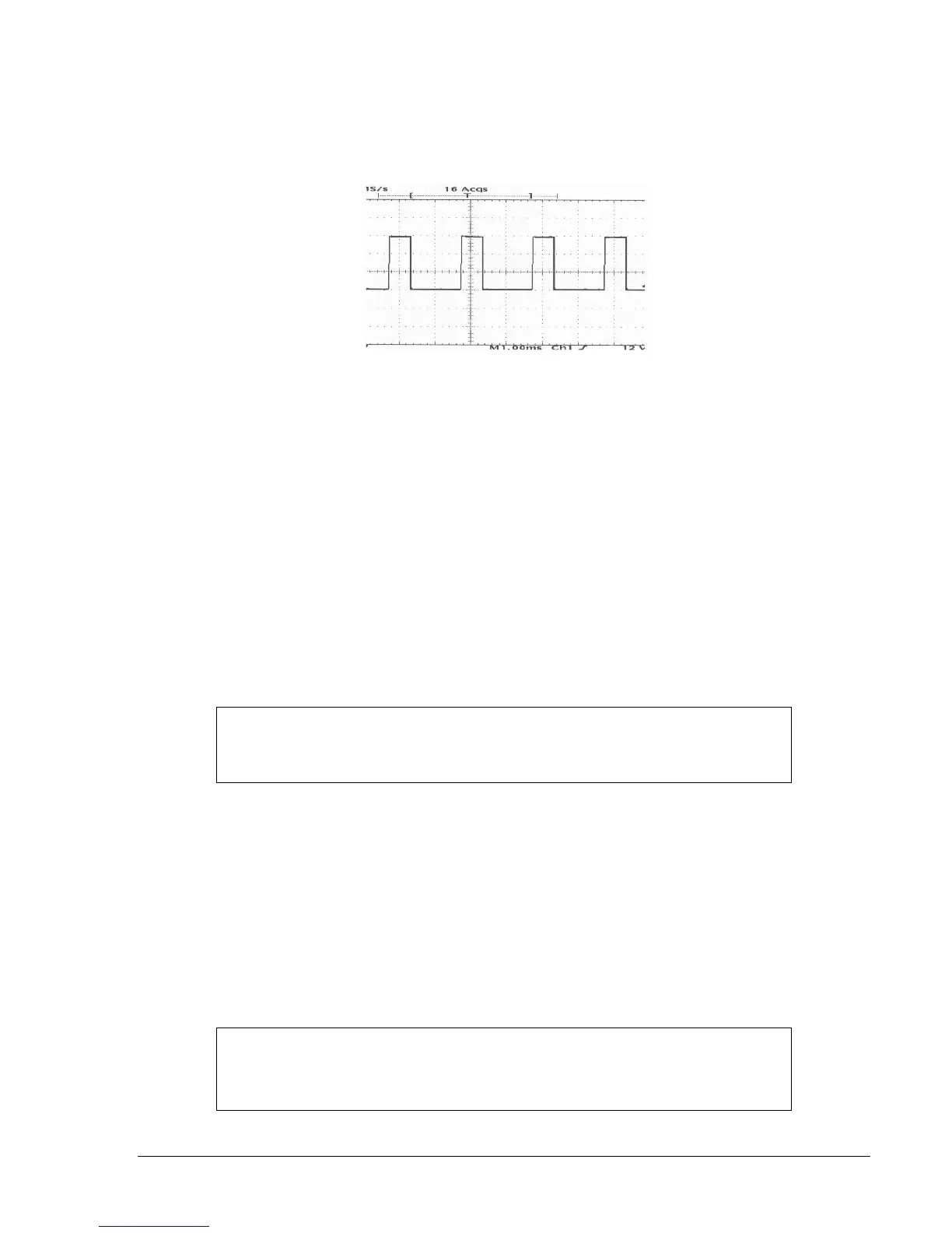
Use an oscilloscope to check the field voltage for proper output (see Figure 6-17)..................... ________
Figure 6-17. Field Voltage Output Waveform
Use a voltmeter to check for correct voltage at generator sensing voltage terminals A1 (E1),
A2 (E2), and A3 (E3)..................................................................................................................... ________
Measure the PT secondary voltages ............................................................................................ ________
Use the Raise/Lower control to raise the terminal voltage to the rated generator level ............... ________
Place the Start/Stop switch in the Stop position and let the generator voltage decrease to
the residual level ........................................................................................................................... ________
Place the Start/Stop switch in the Start position to initiate buildup again in FCR mode .............. ________
Record the voltage buildup characteristic as it reaches full, rated output .................................... ________
Using the BESTCOMS Analysis Screen, perform 5% step change in FCR mode....................... ________
Decrease value, then increase the value. Observe stable performance with chart recorder. ...... ________
Note the Overshoot and settling time. (The FCR output should be very stable.) ......................... ________
Verify that the AVR setpoint tracks the FCR setpoint, then transfer. During this test, use the
Verify that FCR autotracking follows, and is nulled to AVR, then transfer ................................... ________
Use a chart recorder or BESTCOMS oscillography to perform a step response in AVR mode ... ________
Review the PID numbers .............................................................................................................. ________
On the System Options tab of the BESTCOMS System Configuration screen, turn all
limiters off...................................................................................................................................... ________
Perform a 2% voltage step response and record performance to verify stability ......................... ________
Adjust the PID values until desired performance is achieved. If performance appears stable,
repeat step change at 5%.. ........................................................................................................... ________
NOTE
In the following steps, verify that, if the pre-position setpoint is enabled, the
setpoint changes to the assigned value.
NOTE
Assuming Te (exciter field) is known (as applicable for exciter field voltage
regulator applications), increasing Kg will decrease the response time of the
generator. See Figure 6-21.