Image Acquisition Control AW00089317000
146 Basler ace GigE
You can use the Basler pylon API to set the Exposure Overlap Time Max Abs parameter value from
within your application software. The following code snippet illustrates using the API to set the
parameter value:
Camera.ExposureOverlapTimeMaxAbs.SetValue( 3000 );
You can also use the Basler pylon Viewer application to easily set the parameters.
For more information about
the pylon API and the pylon Viewer, see Section 3 on page 45.
the electrical characteristics of the camera’s output line, see Section 5.8 on page 67.
Frame Trigger Wait Signal Details
(All Models Except acA1920-25gm/gc and acA2500-14gm/gc)
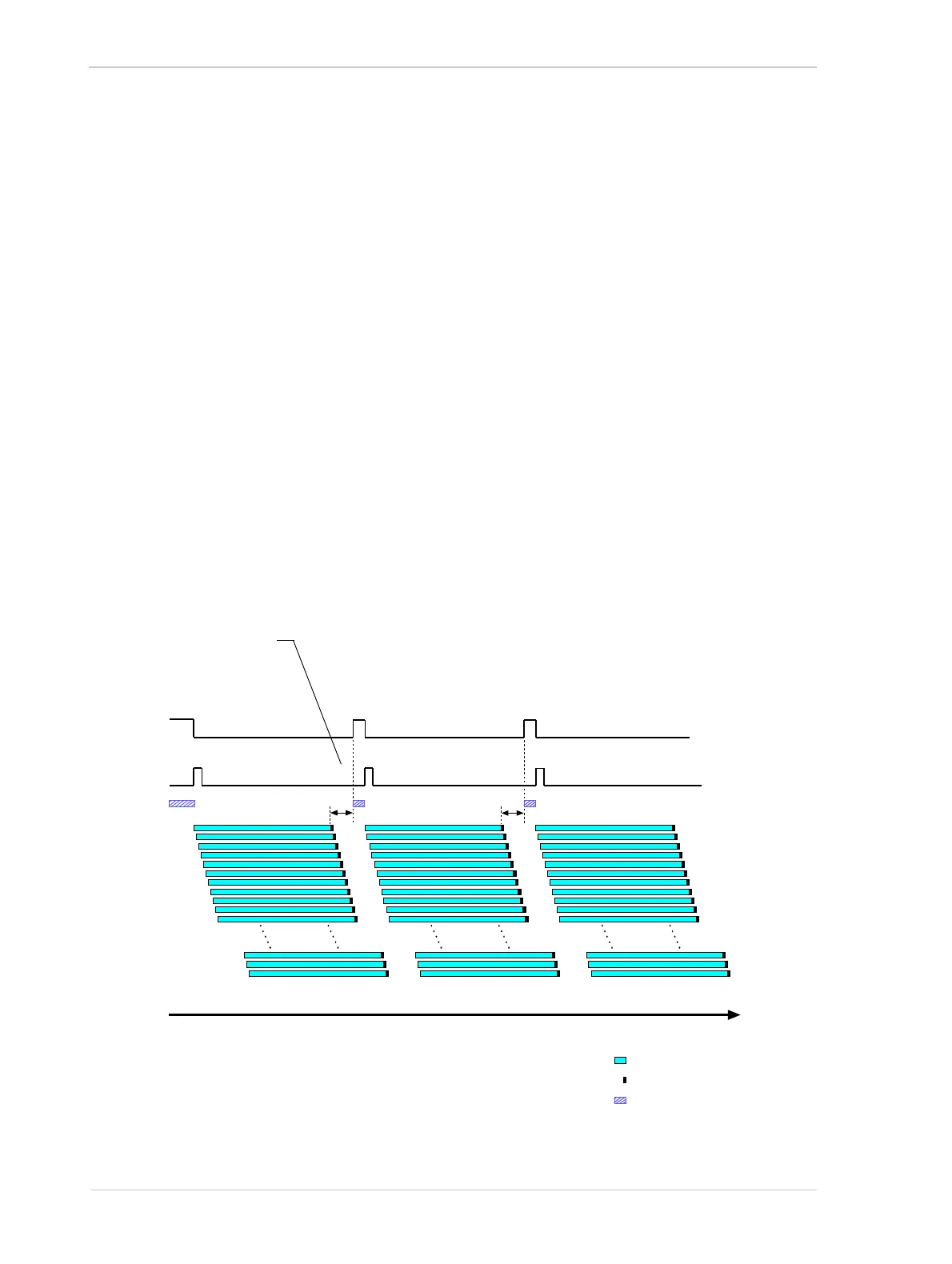
For cameras with a rolling shutter, the rise of the Frame Trigger Wait signal is based on the minimum
time required between the end of exposure of the first line in a frame and the start of exposure for
the first line in the following frame. This functionality is illustrated in Figure 80.
If you are operating a camera with a rolling shutter, you can avoid overtriggering by always making
sure that the Frame Trigger Wait signal is high before you trigger the start of frame capture.
Frame Acquisition N Frame Acquisition N+1 Frame Acquisition N+2
= Line Exposure
= Line Readout
Time
ExFSTrig
Signal
Frame Trigger
Wait Signal
= Camera in a "waiting for
frame start trigger" status
The rise of the Frame Trigger Wait
signal is based on the minimum
time (400 µs) required between the
end of exposure for the first line in
frame N and the start of exposure
for the first line in Frame N+1
Fig. 80: Frame Trigger Wait Signal on a Rolling Shutter Camera

 Loading...


