Chapter 7 DISASSEMBLY/ASSEMBLY PROCEDURES
7 - 14
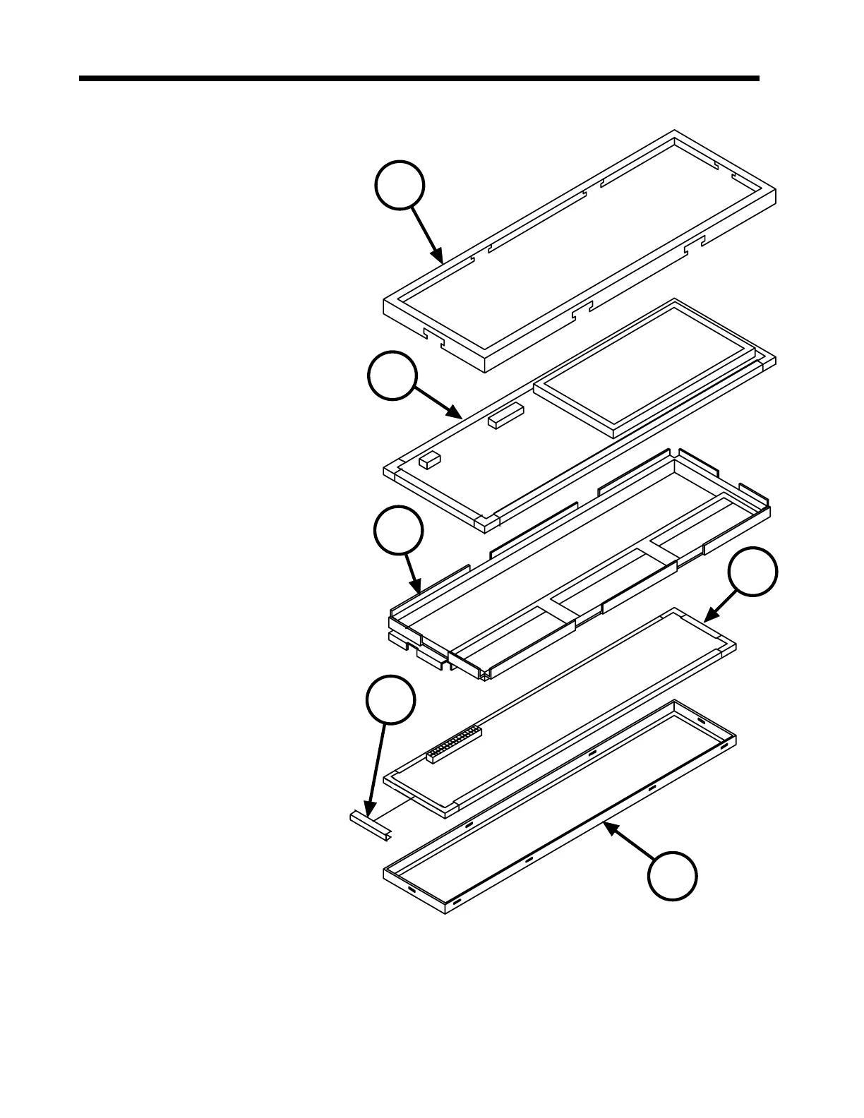
7.2.8 Analog and Digital PCB Assemblies
1. Remove the End Caps, Pole
Clamp, Battery Stack, and
Barrel Clamp by following the
procedures in sections 7.2.1
through 7.2.4.
Separate the Top Cover
Assembly from the Case
Assembly as described in
section 7.2.5.
Remove the PCB assemblies
from the Top Cover/Window
Assembly as described in section
7.2.6.
Although it is not necessary, it is
advised to remove the Keypad
from the Digital/LCD Assembly as
described in section 7.2.7.
2. With the Digital/LCD Assy. (1)
resting on a smooth surface
(grounding mat, etc.), use a small
flat bladed screwdriver to unsnap
the Analog PCB Retainer (2) from
the Electronic Chassis (3) and set
aside the retainer. Observe that
the Analog PCB Assembly is
protected on all four sides by
Conductive Gasket material (4).
3. The Analog PCB Assembly (5)
has a hard wired header on its
unexposed side which is
plugged into the Digital Board
assembly (1). Using a non-
metallic tool having no sharp
edges (i.e., soldering aid tool),
loosen the Analog PCB
Assembly (5) from this
connector.
6
1
3
4
5
2
Figure 7-12 Analog and Digital PC Board Assemblies
 Loading...

