DISASSEMBLY/ASSEMBLY PROCEDURES Chapter 7
7 - 9
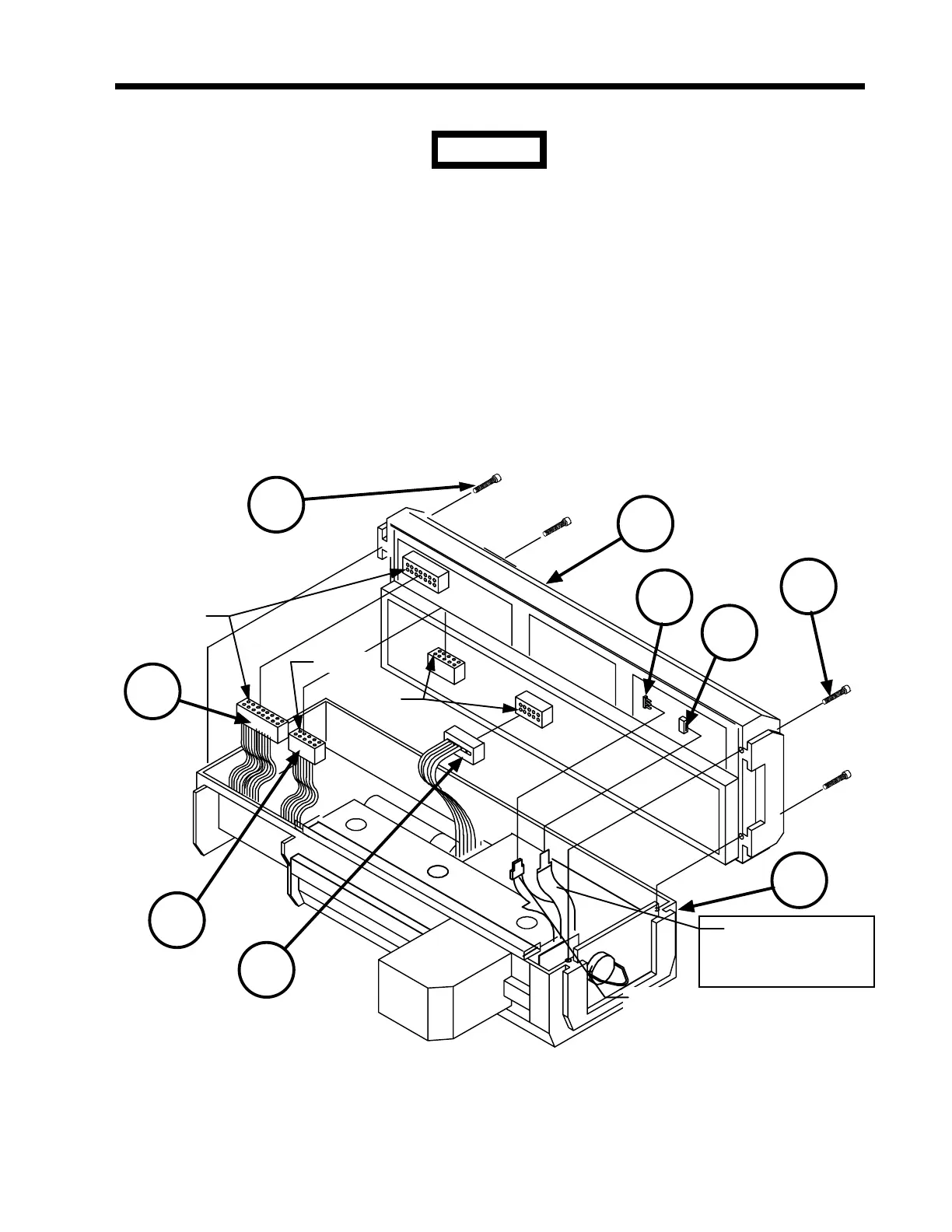
7.2.5 Cover and Case Assemblies (refer to Figures 7-8 and 7-9)
Three ribbon cables and two flexible cables electrically connect the
Cover Assembly (2) to the Case Assembly (3). To prevent any of
these cables from sustaining damage, exercise extreme care when
separating or joining these assemblies.
1. Remove the End Caps by following the procedure in section 7.2.1.
Remove the Pole Clamp by following the procedure in section 7.2.2.
Remove the Battery Stack by following the procedure in section 7.2.3.
Remove the Barrel Clamp by following the procedure in section 7.2.4.
2. Remove the four screws (1) holding the Cover Assembly (2) to the Case Assembly (3).
FLEX CABLE WITH
CONNEC
TOR
7
8
3
FLEX CABLE
WITHOUT
CONNEC
TOR
PIN 1
PIN 1
6
1
PIN 1
5
4
2
1
Figure 7-8 Cover and Case Assemblies
CAUTION
 Loading...

