Chapter 7 DISASSEMBLY/ASSEMBLY PROCEDURES
7 - 10
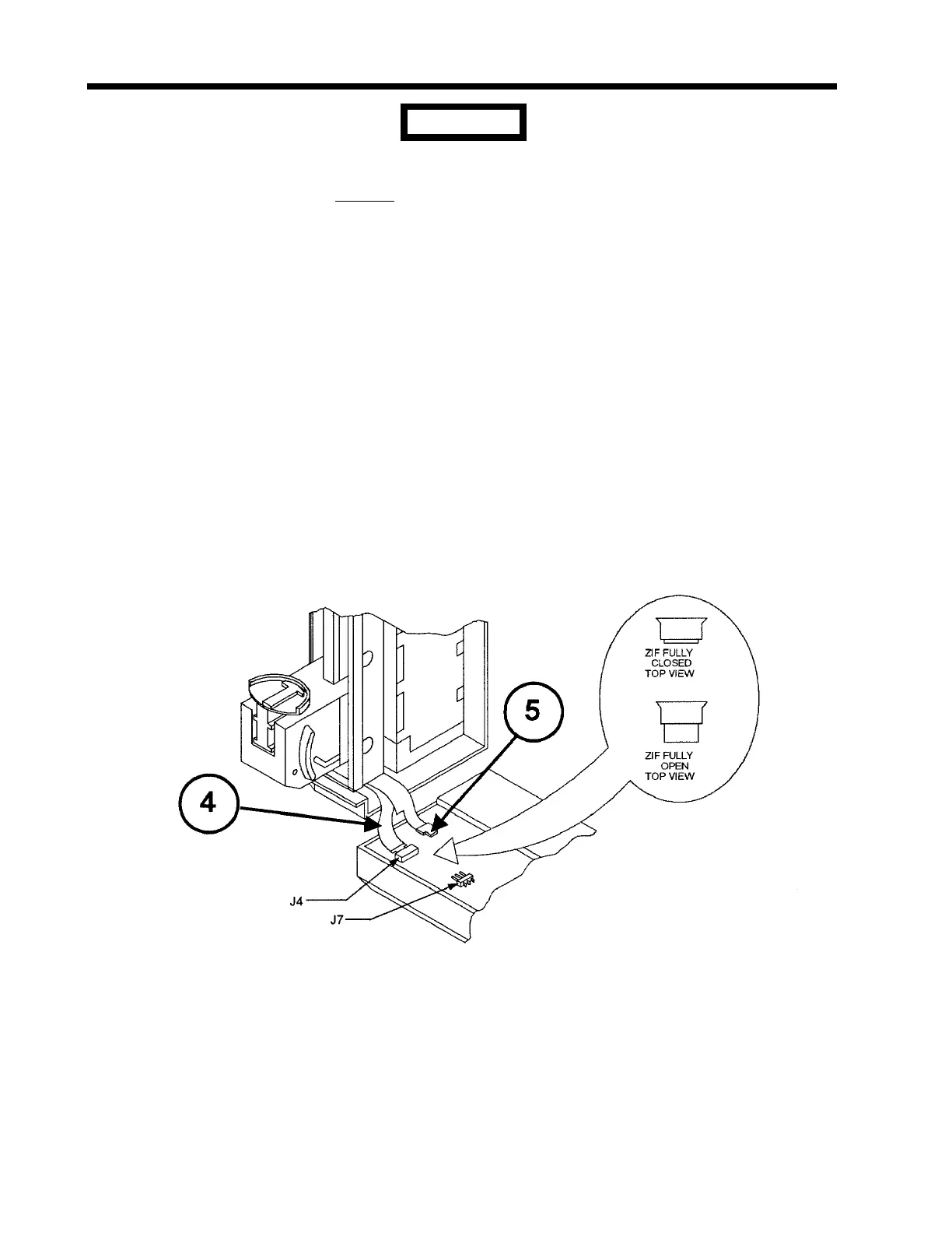
The flexible conduit cables are extremely delicate and must be
handled carefully. Do not bend these cables excessively near their
connectors on the Digital PCB. To properly release the flexible cable
from J4, the ZIF (zero insertion force) connector, the actuator (white
housing) of the connector must be unlocked by sliding it over the
conduit towards the top of the cover. Also, during installation, ensure
that the flexible conduit cable is fully inserted into J4 prior to closing
the actuator. When the cable is fully inserted into J4, none of the
contacts on the cable will be visible.
3. Carefully lift the cover and separate the following connectors:
• J4 ZIF connector (4) on Digital PCB (flex cable without connector);
• J7 connector (5) on Digital PCB (flex cable with connector);
• Sixteen pin ribbon connector (6) on Digital PCB;
• Ten pin ribbon connectors (7) and (8), both on Analog PCB.
Figure 7-9 Flexible Conduit Connections
CAUTION

 Loading...

