DISASSEMBLY/ASSEMBLY PROCEDURES Chapter 7
7 - 13
7.2.7 Keypad Assembly
1. Remove the End Caps, Pole Clamp, Battery Stack, and Barrel Clamp by following the
procedures in sections 7.2.1 through 7.2.4.
Separate the Top Cover Assembly from the Case Assembly as described in section
7.2.5.
Remove the PCB assemblies from the Top Cover/Window Assembly as described in
section 7.2.6.
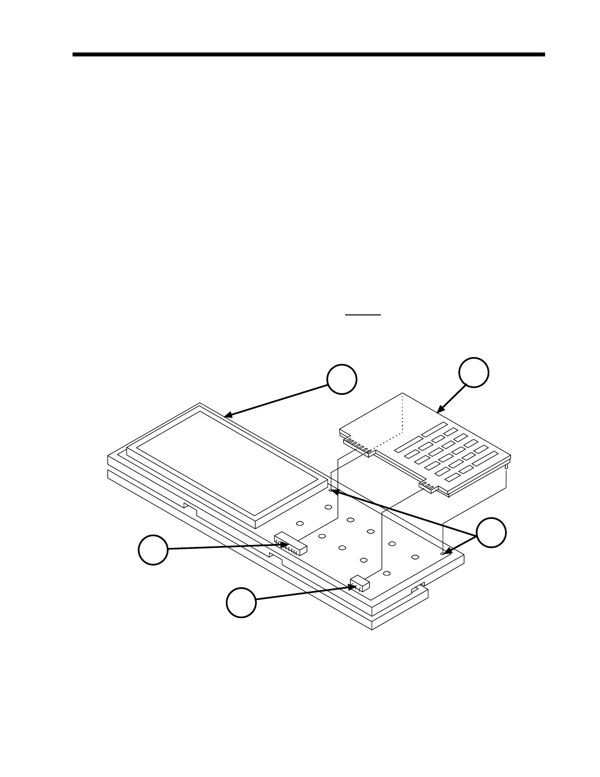
2. The Keypad Assembly (1) is held in place against the Digital/LCD Assembly (2) by two
small metal tabs protruding out from the bottom upper and lower outer corners of the
Keypad’s blank PCB. These tabs, hidden from view, are indexed with and inserted into
two small holes (3) on the Digital/LCD Assembly. Insert a non-metallic tool having no
sharp edges (i.e., soldering aid, etc.) under the edge of the blank PCB to release the
metal tabs from the Digital/LCD Assembly (2).
3. Grasp the right side of the Keypad Assembly (1) and pull it away from the three pin (4)
and ten pin (5) connectors on the Digital board. Do not use excessive force during the
removal process.
1
2
3
4
5
Figure 7-11 Keypad Assembly
 Loading...

