THEORY OF OPERATION Chapter 2
2 - 7
2.2 ELECTRICAL
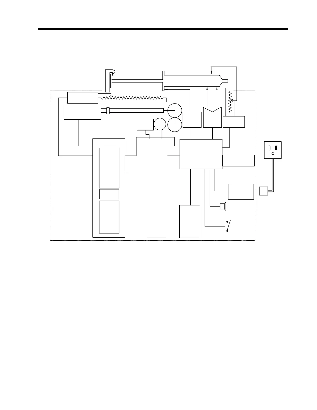
2.2.1 General System Block Diagram
2.2.2 General Description
The Auto Syringe® AS50 Infusion Pump is a computer controlled syringe driving infusion
pump.
A side mounted switch controls the power to the system.
The pump controls the rate of advance of the syringe plunger via program parameters.
Program parameters are entered via a keypad, TTL serial port or RS-232-C serial port and
displayed on the LCD. Operational status is reported on the LCD, the LED status
indicators and by the Audio Transducer.
Syringe capture is determined by three separate sensors. The barrel sensor is made up of
two switches under the rubber pads in the barrel clamp cradle. Both switches must be
closed to detect the barrel presence. The syringe tab is sensed by the barrel clamp which
closes a switch when the flange is not present. Plunger capture is determined by a
Barrel
Sensor
Motor
Lead Screw
Drive Position
& Plunger Capture
Senso
r
Plunger Capture Mechanism
Is Mechanically Linked
To Drive Position
ot
To Lift Wi
er If Ca
ture
Is Lost
Strain Gauge Board
Force Sensor
Secondary
Tilt Switch
Primary
Encoder
Tab
Sensor
Syringe
Size
DIN PWR
TTL Serial
Port
RS232C
Port
Battery
Assembly
I/O Board
S
rin
e
Audio
Transducer
PWR
Switch
LCD
Assembly
Key Pad
Assembly
Digital Board
LED
Status
Analog
Board
AC
Charger
 Loading...

