ROUTINE MAINTENANCE Chapter 5
5 - 5
5.3 CALIBRATION PROCEDURE
5.3.1 Calibration Overview
The pump includes two calibration modes which allow the biomedical/service technician to
either set or review calibration settings for several pump sensors. Entering access code
5089 initiates the “Calibration Set” mode (covered in this chapter) and permits specific
pump sensor settings to be compared against and set according to acceptable calibration
standards. To check but not alter any previous pump settings, a “Calibration Review”
mode (refer to chapter 4) is also provided and may be selected by entering access code
321.
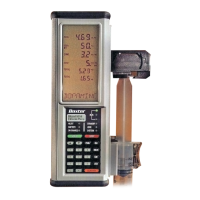
5.3.2 Equipment Needed
• Calibration Fixtures Kit AAS4001803 consisting of the following 7 items:
1. Calibration Fixture CAS4001801
2. Calibration Fixture CAS4002801
3. Calibration Fixture CAS4003801
4. Calibration Fixture CAS4004801
5. Calibration Fixture CAS4005801 (small diameter, unmarked)
6. Calibration Fixture CAS4006801 (large diameter, unmarked)
7. Load Yoke CAS4001802
• IV Pole or equivalent
• 10 lb weight with chain or 100 lb.-test monofilament line
• Variable DC Power Supply
• Multimeter with minimum 5 1/2 digit capability
• Phillips® screwdriver
• Torque screwdriver
5.3.3 Data Recording
It is recommended that a data sheet be kept each time this procedure is run. The data
sheet is located at the end of this chapter. Fill out the pump information at the top of the
data sheet before beginning this procedure. Specific sections in this procedure are
indicated by (*D*) in the text below. This indicates that a recording is required on the data
sheet for that section. As each section is completed, transfer any data collected to the
data sheet and indicate each result as “Pass” or “Fail.”
 Loading...

