Chapter 7 DISASSEMBLY/ASSEMBLY PROCEDURES
7 - 20
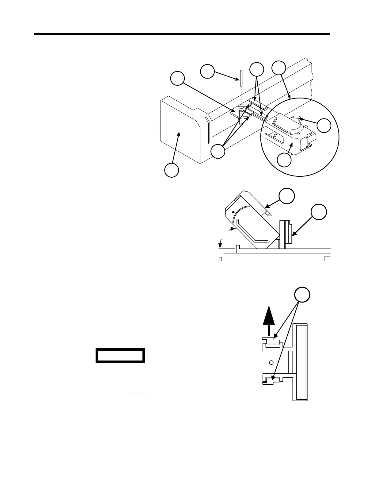
7.2.12 Upper Plunger Assembly
1. Using a 1/16″ punch or
equivalent, push the Lever Pin
(1) out from the Upper Plunger
Assembly (2).
2. Slowly and carefully, pull out the
Upper Plunger Assembly (2)
until the two channels on the
side of the Plunger Driver Slide
(3) separate (disengage) from
the two side rails (4) on the
Plunger Driver Carriage (5).
While keeping these parts
separated, move the Plunger
Driver Slide (3) up towards the
top of the pump (6) and then allow the slide to
rest on the two small flat sections (7) of the
Plunger Driver Carriage (5).
3. Position the pump on the work surface so that
the Plunger Driver Slide (3) faces upward.
Pivot the slide to the left until it comes to rest at
an angle approximately 45° from the
Mechanical Drive Assembly. This action allows
easy access to the Plunger Driver Face (8).
4. Located on the Plunger Driver Carriage (5) are
two interlocking tabs that prevent derailment of
the Plunger Driver Face (8) from the Plunger
Driver Carriage. Defeat these interlocks by
pulling either rail away from the carriage and;
while holding this rail away from the carriage,
slide the Plunger Driver Face (8) out from the
rails.
A Constant Force Spring connects the
Plunger Driver Slide (3) to the Plunger Driver
Face (8). At this time, do not attempt to pull
the Plunger Driver Face (8) away from the
Plunger Driver Slide (3).
5. To separate the Plunger Driver Slide (3) from the Plunger Driver Face (8), use a 1/16″
punch or equivalent to push the Stepped Pin (9) out of the Upper Plunger Assembly (2).
1
2
4
5
6
3
7
8
45
°
8
3
4
Figure 7-15 Upper
Plunger Assembly
CAUTION
 Loading...

