THEORY OF OPERATION Chapter 2
2 - 15
The sensor power of the pump is controlled from U11-19, “SENSOR_PWR*”. It controls
the gate of Q1 a P-Channel MOSFET. The sensor power on the system is switched on
and off to conserve power, especially at low delivery rates.
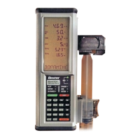
2.2.12.5 Liquid Crystal Display
The LCD display is a custom made STN transflective LCD display panel with alpha-
numeric fields and fixed enunciators. The display is connected to the digital board through
two elastomer zebra strip connectors. The digital board contacts are gold plated to
enhance the reliability of this connection. It is held in place by the LCD frame assembly.
2.2.12.6 LCD Display Driver
The LCD segments are driven by U1 through U3 which is programmed through the “I2C_2”
serial interface bus.
• LCD Contrast Circuit
U22 buffers a voltage generated by R14 and R15 to generate a voltage to bias “VLCD” on
U1 through U3. This voltage controls the potentials provided to the LCD display segments.
• Backlight Current Controller
U12, Q3 and associated components provide a current source to drive the backlight LEDs
D12 and D13. The backlight current is controlled by the master CPU by “BL_EN” either on
or off. The LEDs are Ultra Bright reddish orange devices that shine light into the fiber optic
backlight panel. The backlight is diffused up through the LCD panel by this fiber optic
device to provide an even panel backlight.
 Loading...

