Description
7990044_030_10 – 2078511 – 2023-01-19 23
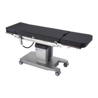
[1] Column keypad
[2] Remote control
[3] Seat section
[4] Back section
[5] Motorized leg section joint with hook coupling for mount L
[6] Side rails for seat section
[7] Motorized back section joint
[8] Side rail for back section
[9] Hook coupling for S support
[10] Insertion opening for traction adapter
[11] Support for the extension adapter
[12] Operating unit connector socket (head and foot ends)
[13] Running gear
[14] Equipotential bonding cable connector pin
[15] Connector socket for power cable
[16] Wheel
[17] Fifth wheel for running gear assistance (directional travel/
drive mode)
[18] Running gear emergency release button (under the label)
[19] Mains power cable
[20] Equipotential bonding cable
[21] Head end of the operating table
[22] Foot end of the operating table
[23] Reset button
[24] Cover cap
[25] Leg section joint side rail (not operating table version U)
[26] Jack props
[27] 2-part cladding protection
 Loading...


