Cube
®
Installation & Startup
5-6 Belanger, Inc. * PO BOX 5470. * Northville, MI 48167-5470 * Ph (248) 349-7010 * Fax (248) 380-9681 1MANUL963
Chapter 5 Getting Started
Installation Overview
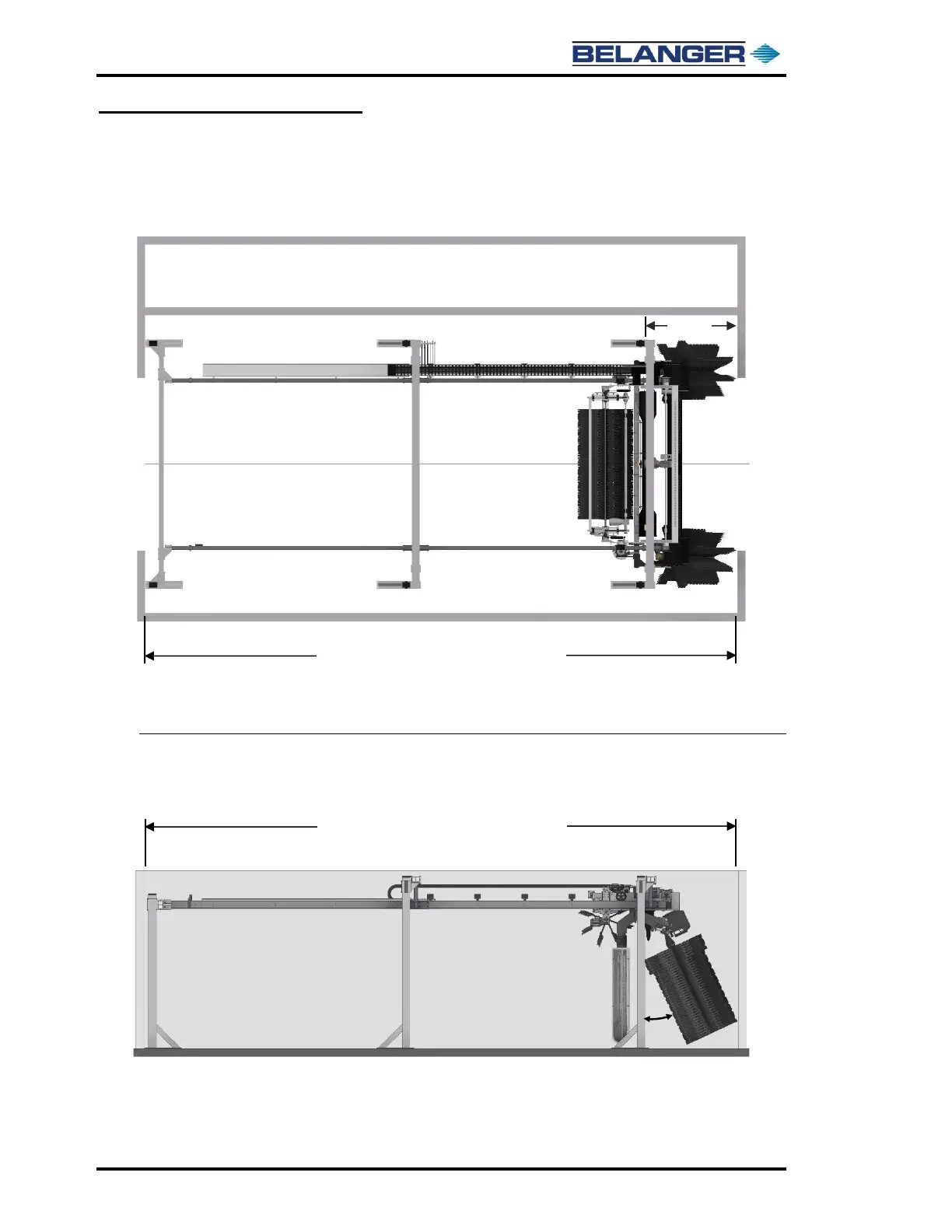
Length Considerations
Cube® Frame in a Minimum Bay Length: Side Wheels at Maximum Rear Tilt (25 degrees)
Cube® Frame in a Minimum Bay Length: Side Wheels at Maximum Rear Tilt
32’ Cube® Frame with Minimum Bay Length 37’-9”
30’ Cube® Frame with Minimum Bay Length 35’-9”
28’ Cube® Frame with Minimum Bay Length 33’-9”
The proportion of each Cube® Frame
to its Minimum Bay Length is as shown.
32’ Cube® Frame with Minimum Bay Length 37’-9”
30’ Cube® Frame with Minimum Bay Length 35’-9”
28’ Cube® Frame with Minimum Bay Length 33’-9”
The proportion of each Cube® Frame
to its Minimum Bay Length is as shown.
Cube® Carriage at
Entrance End Stops
Cube® Carriage at
Entrance End Stops


 To Next Page