EasyManua.ls Logo

Belanger CUBE - Page 64

Default Icon
288 pages
Print Icon
To Next Page IconTo Next Page
To Previous Page IconTo Previous Page
Loading...
Cube
®
Installation & Startup
6-2 Belanger, Inc. * PO BOX 5470. * Northville, MI 48167-5470 * Ph (248) 349-7010 * Fax (248) 380-9681 1MANUL963
Chapter 6 Frame and Carriage Assembly
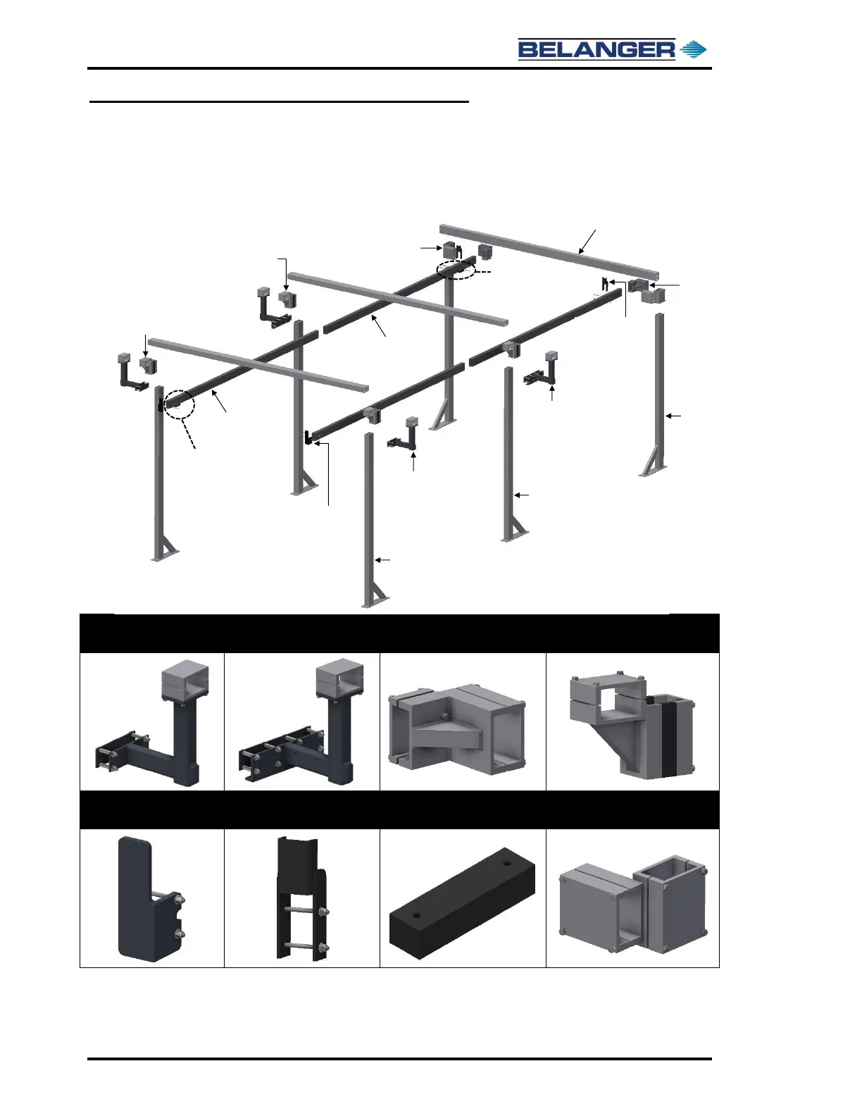
Frame Assembly: Rails and Head Beams
2) Locate the Cube® Frame components and place them in the wash bay. There should be four
(4) Carriage Rails, three (3) identical Head Beams and six (6) Frame Legs. There are also four
(4) Rail L-Brackets assemblies, two (2) exit Rail Support Brackets and six (6) Leg to Head
Beam Bracket assemblies.
Entrance Rail
L-Bracket (2)
Mid Rail L-Bracket (2)
Exit Rail Support Bracket (2)
Entrance & Middle Leg/Head
Beam Bracket (4)
Entrance Safety Stop (2)
Exit Safety Stop (2)
Entrance & Exit
Proximity Target (2)
Exit Leg/Head Beam Bracket (2)
3) The Rail Safety Stops and the Proximity Targets, shown in the chart above, will also be in an
accessory box for the Frame.
Entrance
Rail (2)
Exit Rail (2)
Head Beams (3)
Entrance Legs (2)
Middle Legs (2)
(Same as Entrance Legs)
Exit Legs (2)
(Shorter than other Legs)
Entrance
Leg/Head Beam
Bracket (2)
Exit Rail
Support
Bracket (2)
Entrance Safety
Stop (2)
Entrance Rail
L-Brackets (2)
Mid Rail
L-Brackets (2)
Middle Leg
Head Beam
Bracket (2)
Exit Leg
Head Beam
Brackets (2)
Entrance
Proximity
Target
Exit Prox.
Target
Exit Safety
Stop (2)

Table of Contents

Other manuals for Belanger CUBE