Cube
®
Installation & Startup
1MANUL963 Belanger, Inc. * PO BOX 5470. * Northville, MI 48167-5470 * Ph (248) 349-7010 * Fax (248) 380-9681 6-3
Chapter 6 Frame and Carriage Assembly
Frame Assembly: Rails and Head Beams
4) Verify all the bay length, width, and height considerations highlighted in Chapter 3. Determine
the position of the machine and the centerline of the doors.
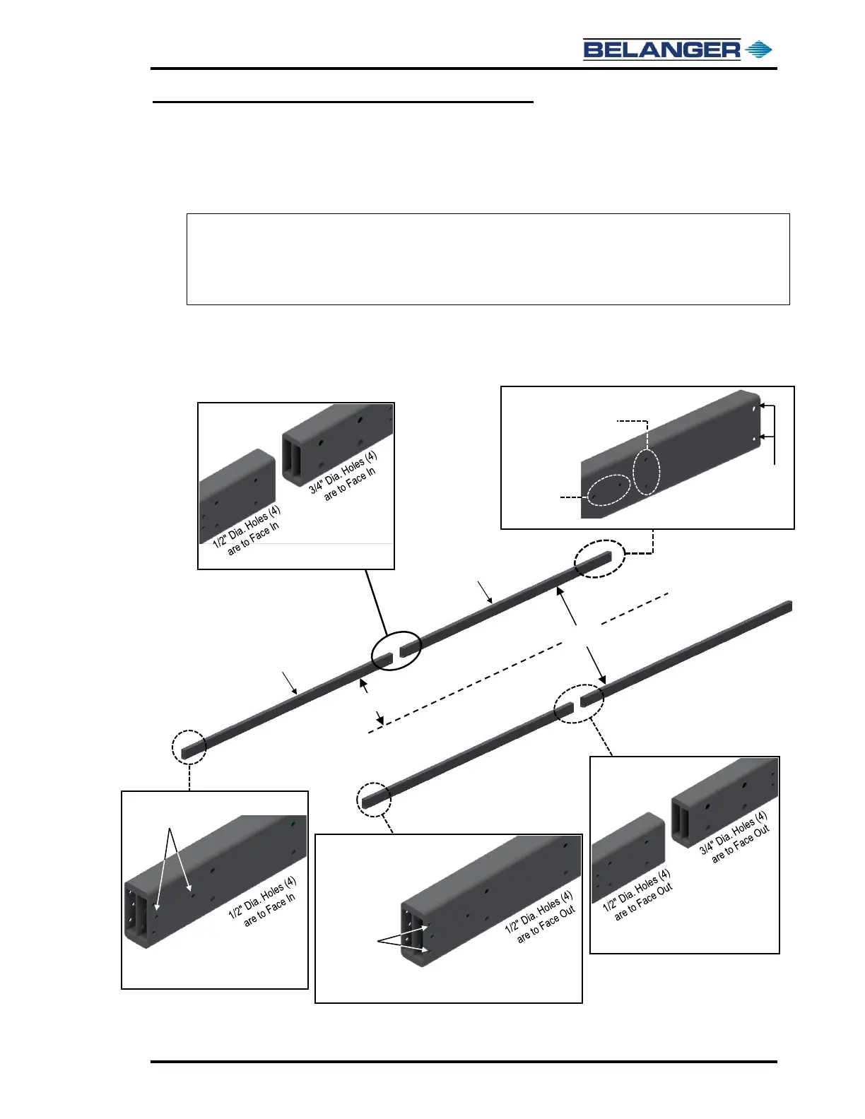
5) Retrieve the two Entrance Rails and two Exit Rails.
6) Layout all four (4) Rails in their approximate installation location and in the proper orientation.
7) Make sure the stamped letter “B” is facing down on all four (4) Rails and are toward the center
of the Frame. Refer to the images below to orient the Rails, confirm mounting hole locations.
Note: The CUBE® has two sets of rails, a set of Entrance Rails and a set of Exit Rails. The Entrance
Rails are identical, and the Exit Rails are identical.
Note: Orientation of the Entrance Rails, the Proximity Target holes must be at the entrance end.
Note: Orientation of the Exit Rails, the Proximity Target holes must be at the exit end and face in.