Cube
®
Installation & Startup
6-4 Belanger, Inc. * PO BOX 5470. * Northville, MI 48167-5470 * Ph (248) 349-7010 * Fax (248) 380-9681 1MANUL963
Chapter 6 Frame and Carriage Assembly
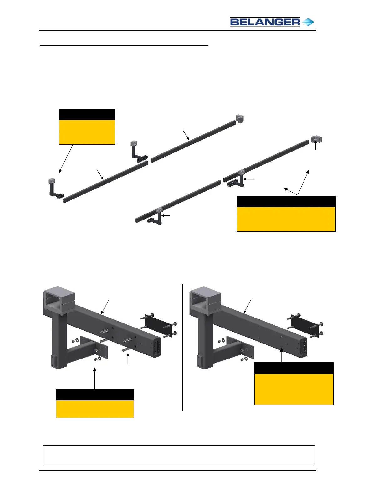
Frame Assembly: Rails and Head Beams
8) Place the Entrance Rail L-Bracket assemblies at the entrance side of the Entrance Rails in the
orientation shown below. The Entrance L-Brackets have a smaller mount plate with only a 4-
hole mount pattern.
9) Place the two Mid Rail L-Brackets at the junction of the entrance and exit rails and place the
Exit Support Brackets at the end of the Exit Rails as shown in the image above.
10) Take the four (4) L-Bracket assemblies apart as shown below in the image on the left.
11) Slide the Compression Rods into the 3/4" diameter holes on each of the Rails, as shown above
in the image on the right. Repeat for each of the L-Bracket locations.
Place the Mid Rail L-Brackets at the junction
of the Rails and the Exit Rail Support Brackets
at the end of the Exit Rails.
Slide the Compression Rods into the
3/4" Dia. Holes on the surface of the
Rails at each L-Bracket mounting
location.
Note: At the junction, where the Mid Rail L-Brackets are installed, the 3/4” Mounting Holes on the
Exit Rails will be on the opposite side as the 3/4” Mounting Holes on the Entrance Rails.
 Loading...