EasyManua.ls Logo

Belanger CUBE - Page 67

Default Icon
288 pages
Print Icon
To Next Page IconTo Next Page
To Previous Page IconTo Previous Page
Loading...
Cube
®
Installation & Startup
1MANUL963 Belanger, Inc. * PO BOX 5470. * Northville, MI 48167-5470 * Ph (248) 349-7010 * Fax (248) 380-9681 6-5
Chapter 6 Frame and Carriage Assembly
Frame Assembly: Rails and Head Beams
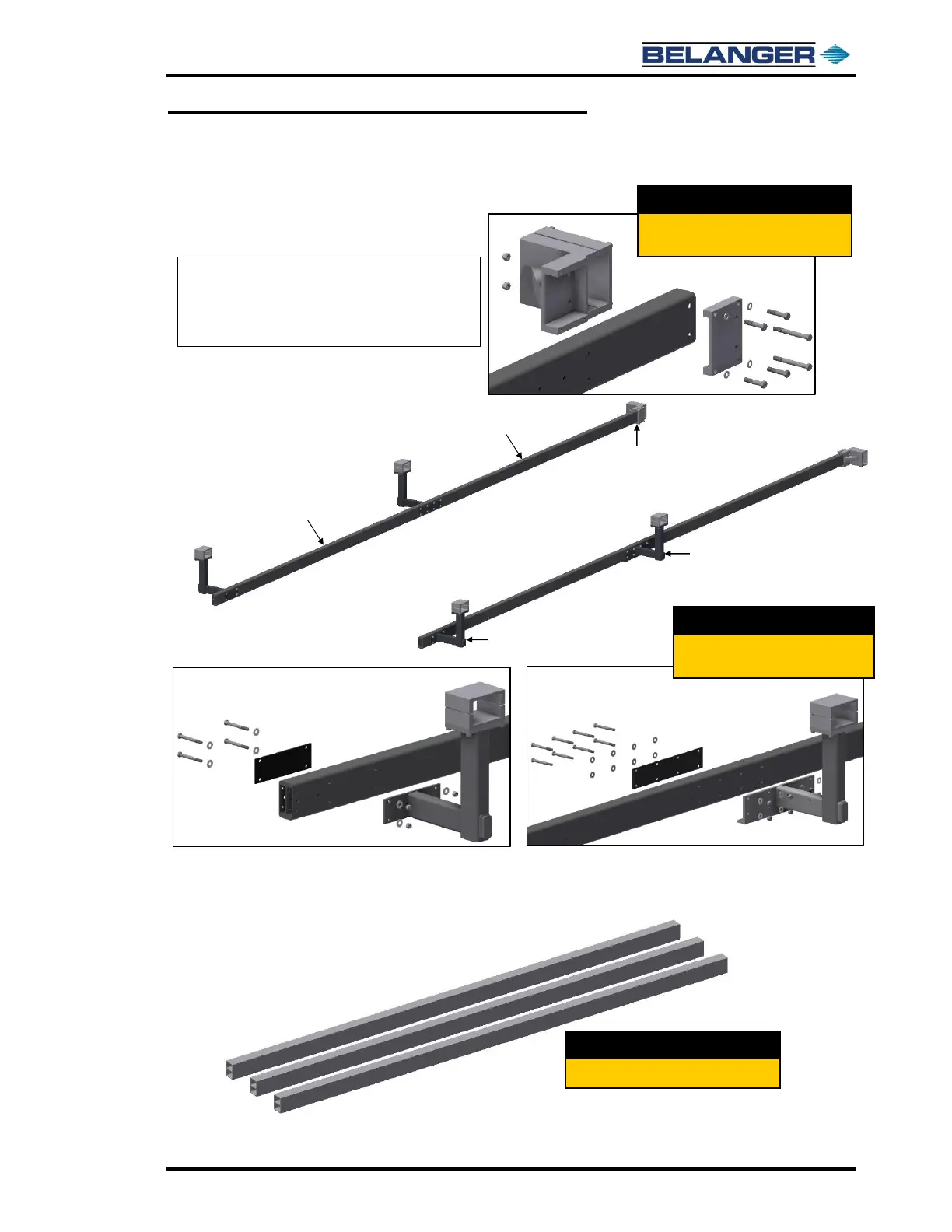
12) Attach the four (4) L-Brackets to the frame using the 1/2-13 x 4-3/4‘’ bolts, 1/2‘’ flat washers,
and 1/2’’ Nylock™ nuts, as shown below.
13) Attach the two (2) Exit Rail Support Brackets to the Exit Rails as shown above.
14) Retrieve the three (3) Head Beams.
Exit
Entrance
Entrance
Rail (2)
Exit Rail (2)
Exit Rail
Support
Bracket (2)
Mid Rail
L-Brackets (2)
Entrance Rail
L-Brackets (2)
Mid Rail L-Bracket Assembly
Entrance Rail L-Bracket Assembly
Step 13:
Assemble the Exit Rail Support Brackets
to the end of the Exit Rails.
Step 12:
Assemble the Entrance and Mid Rail
L-Brackets to the Rails.
Step 14:
Locate the three (3) 190” Head Beams.
Note: All bolt heads on L-Brackets and
Exit Rail Support Brackets are to be
on the inside of rails and nuts are on
outside of rails.

Table of Contents

Other manuals for Belanger CUBE