Cube
®
Installation & Startup
6-6 Belanger, Inc. * PO BOX 5470. * Northville, MI 48167-5470 * Ph (248) 349-7010 * Fax (248) 380-9681 1MANUL963
Chapter 6 Frame and Carriage Assembly
Frame Assembly: Rails and Head Beams
15) If the width between the bay walls is less than 190” apart, the Head Beams must be cut down.
16) Mark the Head Beams centerlines taking into account the machine position according to the
“Position Consideration Chart” in Chapter 3.
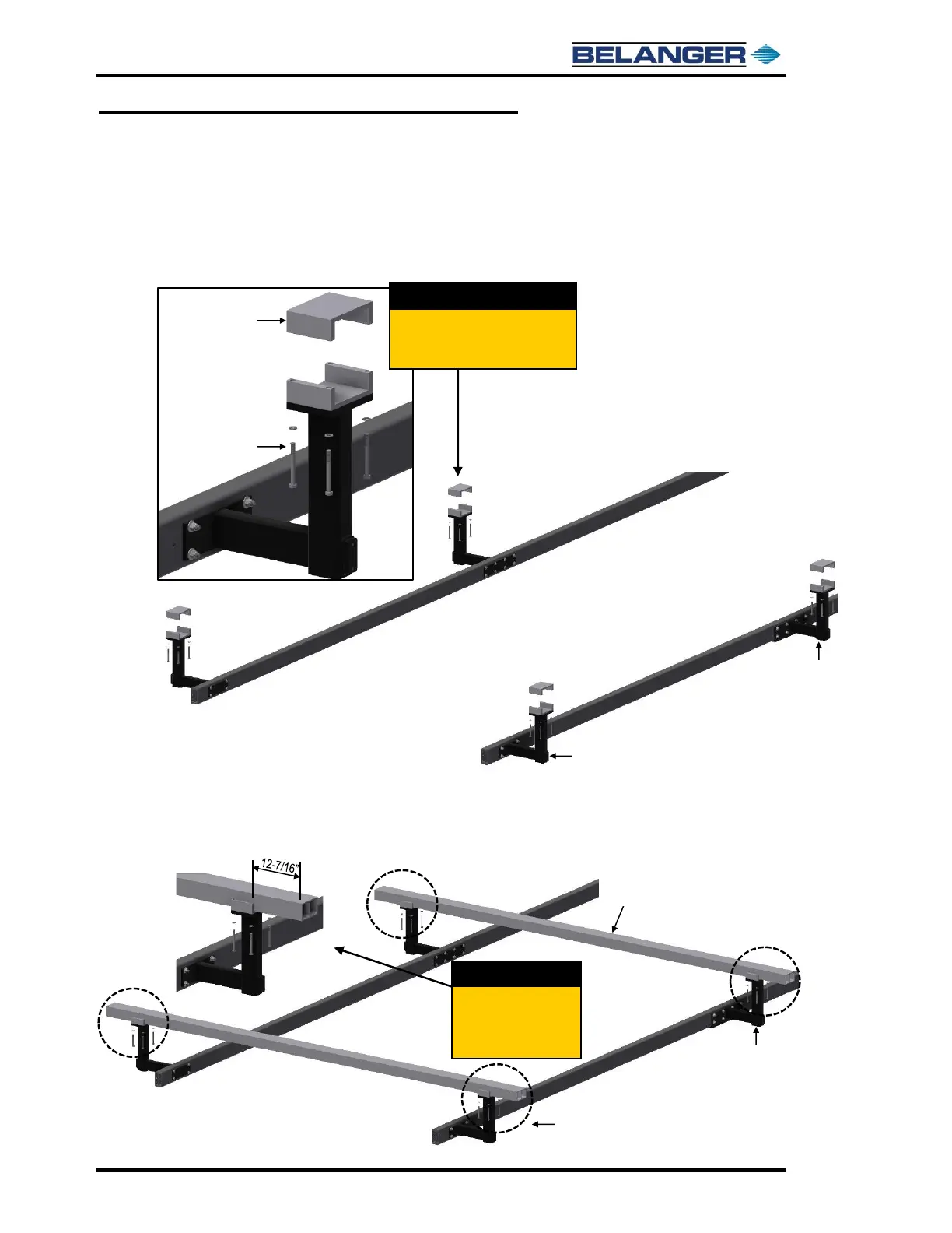
17) On the entrance and middle L-Brackets remove the Head Beam Clamp fasteners and the top
half of the Head Beam Clamp, shown below.
18) Lay the Head Beams into the Clamps on the Entrance and Mid L-Brackets and center the Head
Beams across the Frame. Verify that the distance between the end of each Head Beam and
the outer face of the Clamp is 12-7/16”, shown below.
Remove the Head Beam Clamp
fasteners and the top half of the
clamps on all the L-Brackets.
 Loading...