Cube
®
Installation & Startup
6-8 Belanger, Inc. * PO BOX 5470. * Northville, MI 48167-5470 * Ph (248) 349-7010 * Fax (248) 380-9681 1MANUL963
Chapter 6 Frame and Carriage Assembly
Frame Assembly: Rails and Head Beams
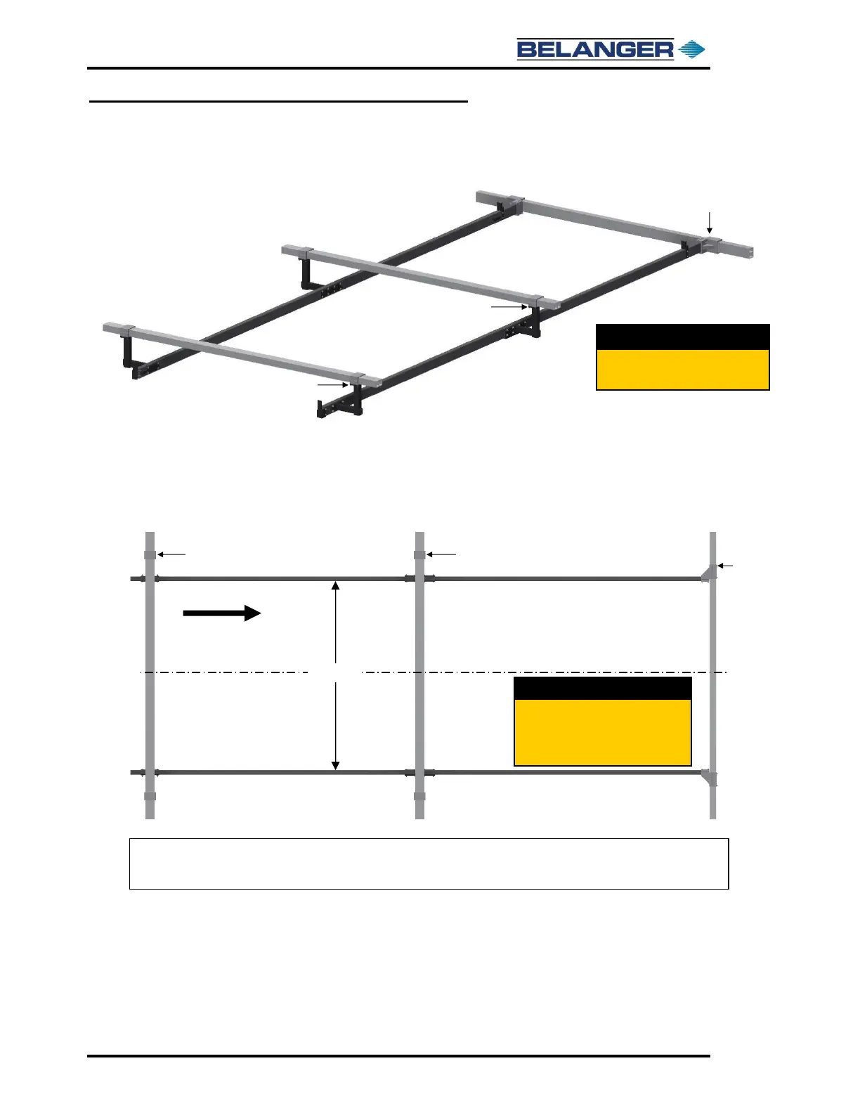
23) On the passenger side, tighten down all the Head Beam Clamp Bolts.
24) Confirm again that the Head Beams are centered, the center of the Head Beams to the inside
of each rail should measure 62-1/2”.
25) Check that the rail spacing is 125” in several locations, make adjustments if necessary and
then tighten the driver side Head Beam Clamps down completely.
Verify all Head Beams are centered
across Frame. Confirm Rails are
spaced 125” apart then tighten down
driver side Head Beam Clamps.
 Loading...