Cube
®
Installation & Startup
1MANUL963 Belanger, Inc. * PO BOX 5470. * Northville, MI 48167-5470 * Ph (248) 349-7010 * Fax (248) 380-9681 6-9
Chapter 6 Frame and Carriage Assembly
Frame Assembly: Rails and Head Beams
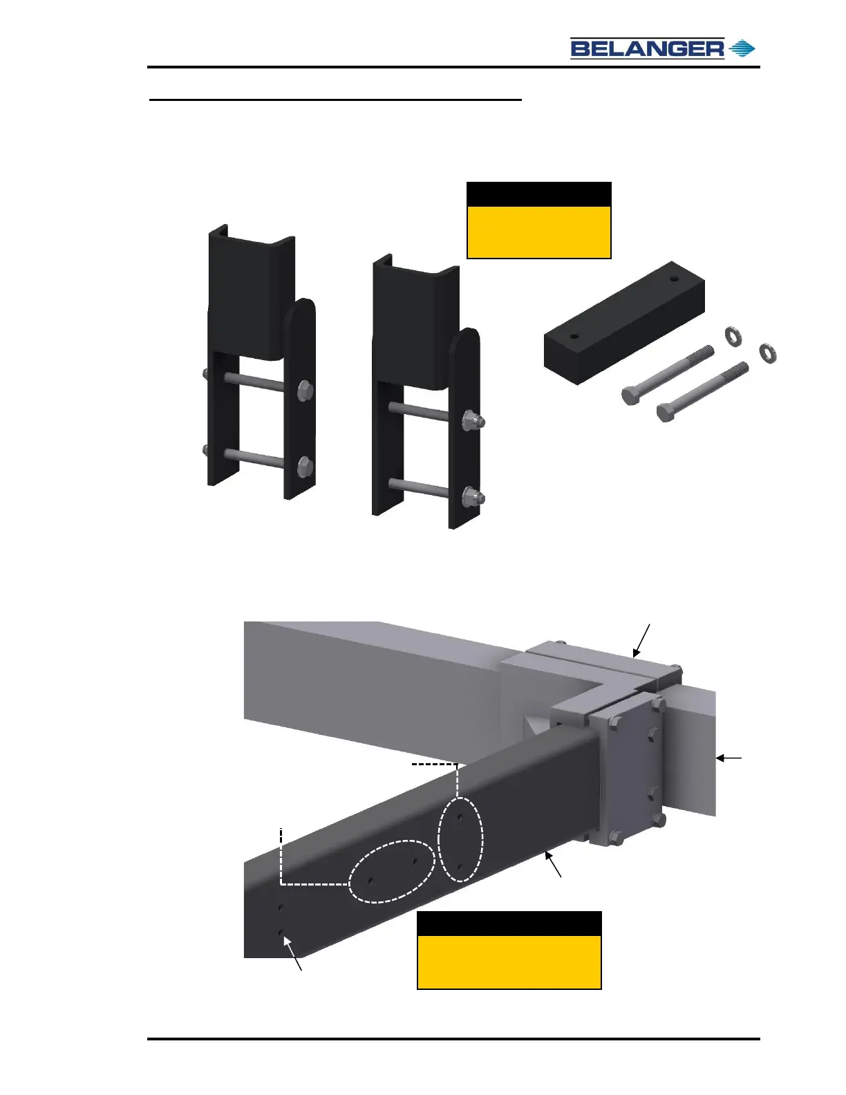
26) Retrieve the two (2) Exit Rail Safety Stops with fasteners and the other Proximity Target and
two fasteners. Apply a small amount of Red Loc-Tite™ to the fasteners for the Safety Stops.
27) The Exit Safety Stops and Exit Proximity Target are to be mounted on the Exit Rails using the
holes toward the end of the Exit Rails, refer to the image below for clarity.
In the Accessory Box for the
Frame Assembly locate the
parts shown in these images.
Locate the mounting holes at the end
of the Exit Rails for the Exit Safety
Stops and the Proximity Target.