Cube
®
Installation & Startup
6-10 Belanger, Inc. * PO BOX 5470. * Northville, MI 48167-5470 * Ph (248) 349-7010 * Fax (248) 380-9681 1MANUL963
Chapter 6 Frame and Carriage Assembly
Frame Assembly: Rails and Head Beams
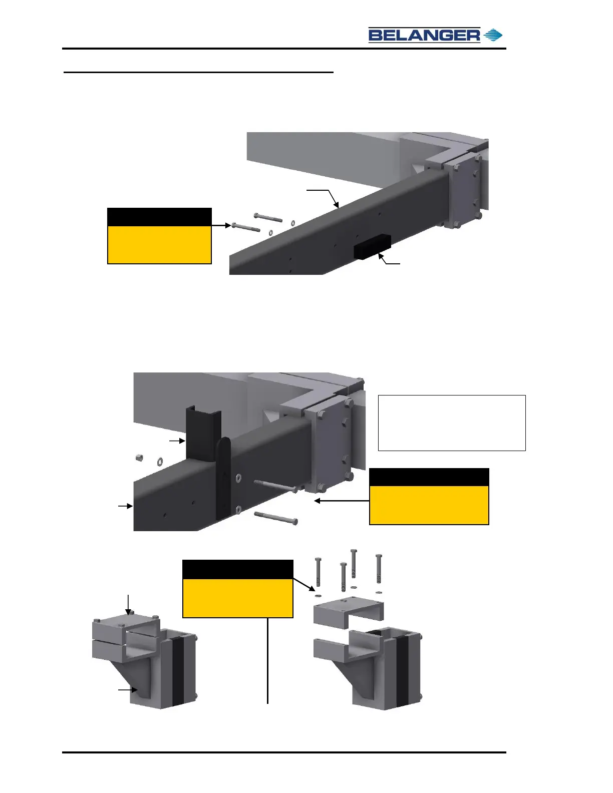
28) Secure the Exit Proximity Target to the inside face of the driver side Exit Rail in the location
shown in the image below.
29) Secure the Exit Safety Stops to both Exit rails as follows:
➢ Orient the Safety Stops so that they are on top of the Exit Rails with the Stop Post facing
the center of the bay so that it will make contact with the Rollers on the Carriage.
➢ Insert the 3/8” bolts through the Safety Stop and the pre-drilled holes in the Exit Rails.
➢ Using the 3/8 x 4-1/2” bolts, washers and 3/8” lock nuts secure the Safety Stops to the
Rails.
30) Locate the four (4) Leg/Head Beam Brackets for the Entrance and Middle Head Beam.
31) Remove the fasteners and the top half of the Head Beam Clamp on the Brackets.
Note: Secure the Stops with the
bolt heads on the inside of
rails and nuts on outside
of rails.