Cube
®
Installation & Startup
6-12 Belanger, Inc. * PO BOX 5470. * Northville, MI 48167-5470 * Ph (248) 349-7010 * Fax (248) 380-9681 1MANUL963
Chapter 6 Frame and Carriage Assembly
Frame Assembly: Rails and Head Beams
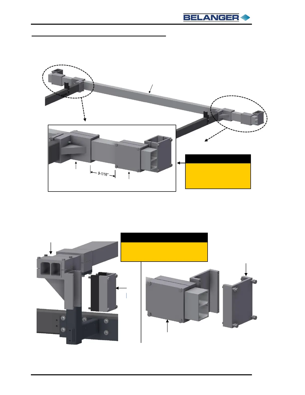
34) Attach the Exit Leg/Head Beam Brackets onto the Head Beam at the exit of the bay, see
images below.
35) Position the Exit Leg/Head Beam Brackets with the edge of the Head Beam Clamp 9-1/16”
from the edge of the Exit Rail Support Bracket. Refer to the image above.
36) Remove the fasteners and half of the Leg Clamps on all the Leg/Head Beam Brackets as
shown below. These brackets will be reassembled when attaching the Legs to the Frame.
37) The top portion of the Frame Assembly is now ready to be lifted up to attach the Leg
Assemblies.
Attach the Leg/Head Beam Brackets
to the Exit Head Beam with the clamp
the specified distance from the Exit
Rail Supports.
.
On the six (6) Leg/Head Beam Brackets, remove
half of the Leg Clamp and set aside until the Legs
are to be attached to the frame.