Cube
®
Installation & Startup
6-18 Belanger, Inc. * PO BOX 5470. * Northville, MI 48167-5470 * Ph (248) 349-7010 * Fax (248) 380-9681 1MANUL963
Chapter 6 Frame and Carriage Assembly
Frame Assembly: Position Frame in Bay
Establish Lines in Bay to Position the Frame Assembly
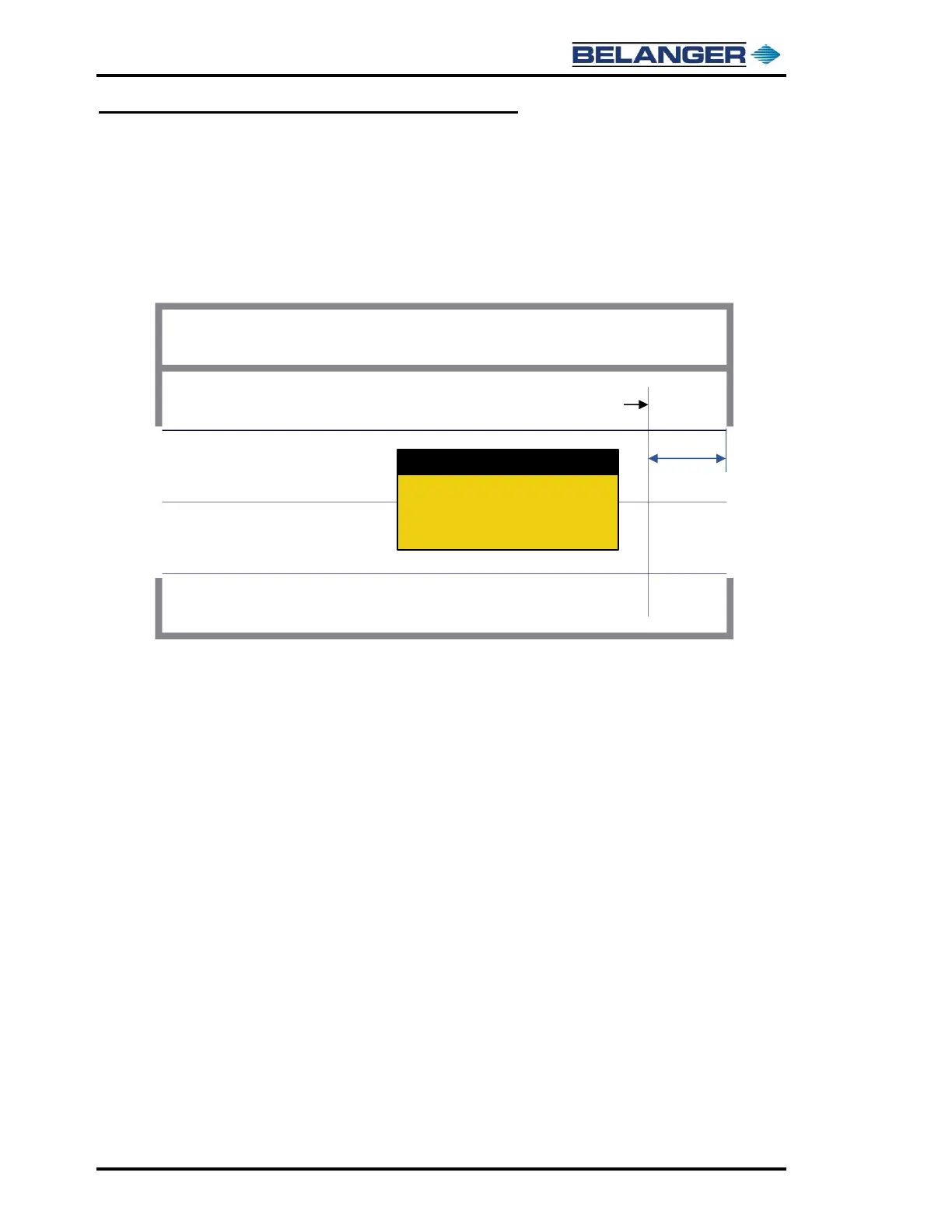
9) The recommended set back dimension from the entrance of the bay for ALL Frame Assembly
lengths (28’, 30’ or 32’ Frame Assemblies) is a minimum of 68-1/4”.
This dimension should be taken from the inner most object on the entrance side. It could be
the wall, the door, or some other object in the bay. Basically, anything that the Side Wheels
could come in contact with during operation is where to measure from.
10) Mark this distance on both the driver side and passenger side chalk lines in the bay.
11) Align and snap a chalk line between these points at the entrance of the bay. This line will be
used to place the front face of the feet on the entrance Leg Assemblies.
Measure a minimum of 68-1/4” from the
interior entrance wall along the DS & PS
chalk lines, mark the spots and snap a
chalk line between the marks.