VC-6000
TM
Compact monitor Part C DC output
- 76 - C100583.002 Components Vers. 07 © VC-6000
TM
Compact monitor Sept. 2011
The Y-values of anchor points corresponds to the desired output signal
with reference to the maximum output signal. The available range is from 0
(corresponding to 0 %) to 1 (correspondig to 100 %). The associated voltage
or current output is dependent on the parameter <Signal output>:
◊ Y-value range: 0.00 ≤ Y ≤ 1.00 (corresponds to: 0 % ≤ Y ≤ 100 %)
that means: 0.00 ≤ Y1 < Y2 < Y3< Y4 ≤ 1.00
◊ Y-value 0.00 corresponds to 0 %
If no offset has been selected
(<Signal output> = 0-20 mA/0-10 V)
0 % also corresponds to 0 mA/0 V.
If an offset has been selected
(<Signal output> = 4-20 mA/2-10 V) 0 % corresponds to 4 mA/2 V.
◊ Y-value 1.00 corresponds to = 100 % and = 20 mA/10 V
When setting an output curve with 2 anchor points, the following must
be observed:
1. X-values: -99999.99 ≤ X1 < X2 ≤ + 99999.99
2. Y-values: 0.00 ≤ Y1 ≤ 1.00 and : 0.00 ≤ Y2 ≤ 1.00
The maximum output range (0-20 mA or 0-10 V) can be reduced to any
random output range within these limits.
3. X3 = 0.00
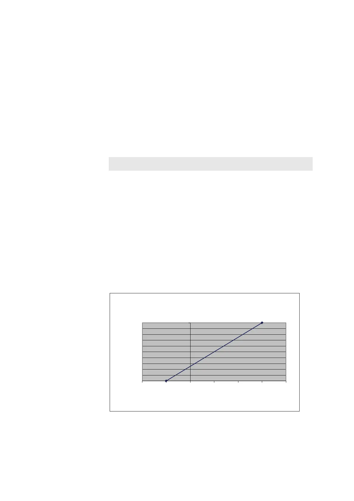
Example:
A measuring range from -5 to + 15 mm is to be represented by an output
signal of 4-20 mA (2-10 V).
Solution: X1 = -5.00, Y1 = 0.00, X2 = 15.00, Y2 = 1.00, X3 = 0.00
To achieve this the parameter ‘Signal output’ must be set to
4-20 mA / 2-10 V.
False entries are corrected by simply overwriting the values.
0,00
0,10
0,20
0,30
0,40
0,50
0,60
0,70
0,80
0,90
1,00
-10,00 -5,00 0,00 5,00 10,00 15,00 20,00
Y-values
X-values [mm]
Output signal with 2 anchor points