DC output Part C VC-6000
TM
Compact monitor
© VC-6000
TM
Compact monitor Sept.2011 C100583.002 Components Vers. 07 - 77 -
Deleting anchor points:
1. This is only possible and sensible for the anchor points (X3, Y3) and
(X4,Y4), because without (X1, Y1) and (X2, Y2 ) no signal output is
possible.
2. Deleting (X3, Y3): X3-value is set to 0.0; (X4, Y4) will then also be
invalidated
3. Deleting (X4, Y4): X4-value is simply set to 0.0
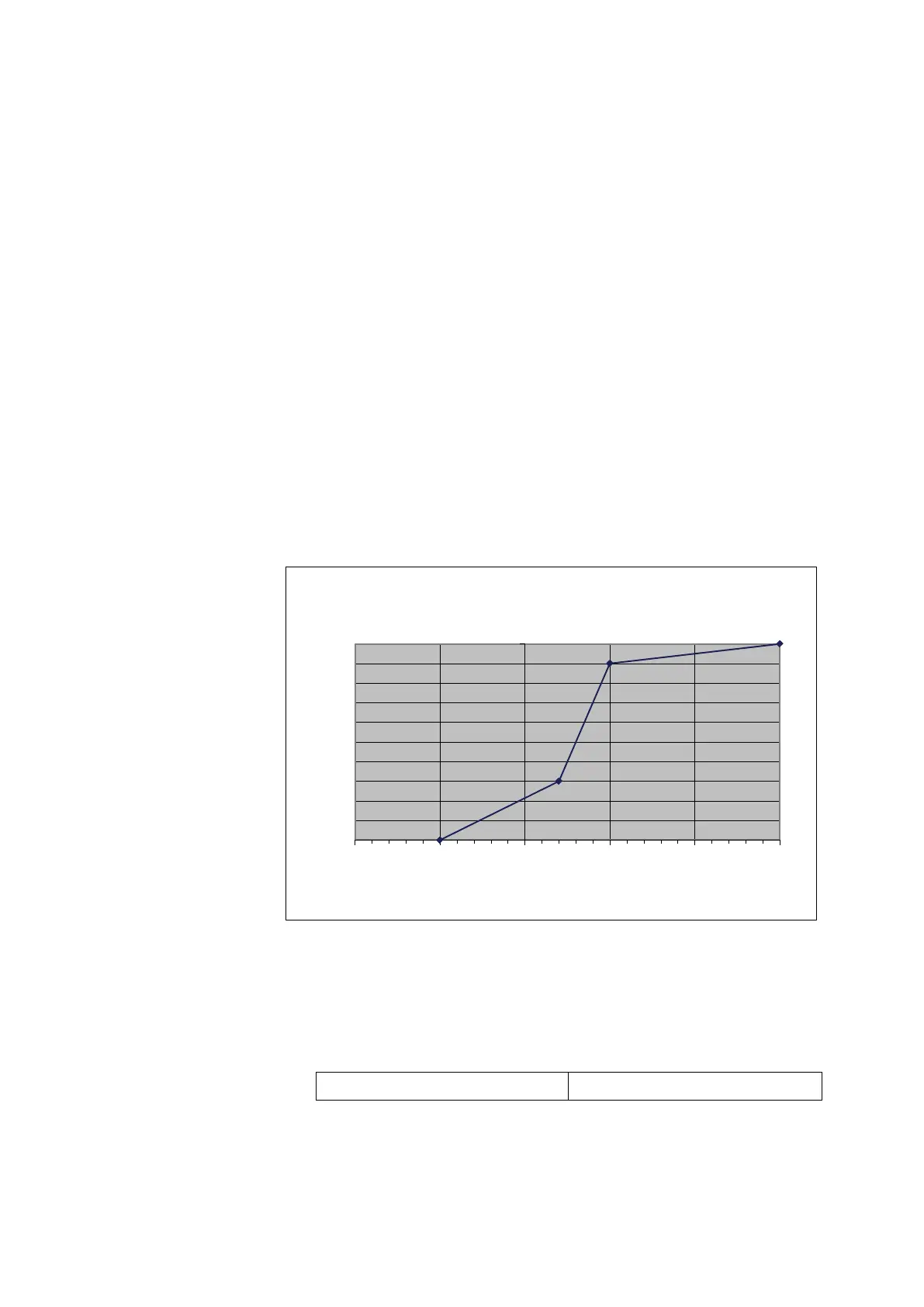
♦ With the definition of a curve with non-linearity (at least 3 anchor
points) a “zoom” range can be provided. Thus a small change in the
measured value leads to a disproportionate change in the output signal
Example:
A measuring range from -5 to + 15 mm is to be spread out in the range from
+ 2 mm to + 5 mm because the measurement is especially important in this
range.
The output signal is to be represented by the range 4-20 mA (2-10 V).
Solution: X1 = -5.00, Y1 = 0.00, X2 = 15.00, Y2 = 1.00,
X3 = 2.00, Y3 = 0.30, X4 = 5.00, Y4 = 0,90
♦ <Hardware Id.>
This parameter informs you about the type of the output module. The
settings are determined by the applicaton firmware of the
VIBROCONTROL 6000 Compact monitor and cannot be changed at the
instrument.
Hardware Id. 4
0,00
0,10
0,20
0,30
0,40
0,50
0,60
0,70
0,80
0,90
1,00
-10,00 -5,00 0,00 5,00 10,00 15,00
Y-values
X-values [mm]
Output signal with 4 anchor points
 Loading...