Setting of limit setpoints and time delays Part D VC-6000
TM
Compact monitor
© VC-6000
TM
Compact monitor Dec 09 C100585.002 Communication Vers. 03 - 31 -
10.6 Putting the DC outputs into operation
10.6.1 Setting the parameters of a linear DC-output
Example:
A measuring range from -5 to + 15 mm should be represented by an output
signal of 4-20 mA (2-10 V).
Solution: X1 = -5.0, Y1 = 0.0, X2 = 15.0, Y2 = 1.0, X3 = 0.0
A detailed explanation of the DC output can be found in the description of
the signal-flow components.
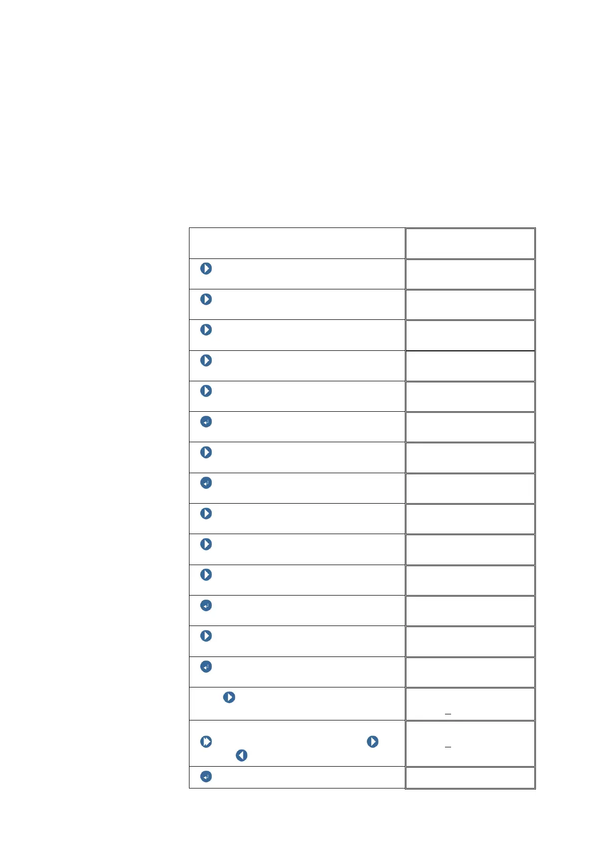
Block level
NEXT
NEXT
NEXT
NEXT
NEXT (until the DC-output appears)
ENTER BUTTON
DC-OUT 01
NEXT
DC-OUT 01
ENTER BUTTON
DC-OUT 01
NEXT
Signal output
NEXT
Signal output
NEXT
Signal output
4-20mA / 2-10V
ENTER BUTTON
DC-OUT 01
NEXT
DC-OUT 01
ENTER BUTTON
X1
With NEXT select the digit position to
be changed.
X1
+00000
.00mm
Changing the digit:
Push and hold SHIFT, then push
NEXT / PREVIOUS to change the digit.
X1
+00005
.00g
ENTER BUTTON
DC-OUT 01
 Loading...